AH-5A BOGEN COMMUNICATIONS, AH-5A Datasheet - Page 72
AH-5A
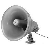
Manufacturer Part Number
AH-5A
Description
Amplified Speaker/horn
Manufacturer
BOGEN COMMUNICATIONS
Datasheet
1.AH-5A.pdf
(88 pages)
Specifications of AH-5A
Peak Reflow Compatible (260 C)
No
Leaded Process Compatible
No
Lead Free Status / RoHS Status
Contains lead / RoHS non-compliant


70
SPEAKER LAYOUT
The layout of the speakers should be planned before installation begins. The spacing of the speakers can be
adjusted so that the speakers are evenly spaced in a row. Some adjustments may need to be made due to sound
obstructions that may be in the area such as high shelving, cubicle walls, etc.
Ceiling Speakers
Layout starts in one corner of the area. The first speaker should
be positioned from each wall a distance approximately equal to
the ceiling height of the room (dimension A).
The next speaker in row 1 should be spaced a distance
approximately equal to twice the height of the ceiling
(dimension B). Each additional speaker in the row should use
this same spacing.
Row 2 starts at twice the ceiling height distance (B) from row 1
and twice the ceiling height (B) from the wall. The other speakers
in this row are also spaced at twice the ceiling height.
Row 3 is again spaced at twice the ceiling height (B) from the
previous row. The first speaker starting this row is positioned at
one ceiling height distance (A) from the wall (similar to row 1).
Continue this pattern of alternating rows until the room is covered.
The spacing of the speakers can be adjusted so that the speakers
are evenly spaced in a row and are more aesthetically pleasing.
Horn Loudspeakers
Desired mounting height, barring obstructions, is 15 to 20 feet,
with the speakers angled downward toward the listening area
and facing in the same direction. Follow the diagram for the
layout of the horn speakers while using the charts below to de-
fine the lettered dimensions for each specific speaker.
Begin in one corner of the area. The first speaker in Row 1 is
positioned a distance equivalent to (1/2 C). The next speaker
in Row 1 should be a distance equivalent to (C) from the first
speaker. Each additional speaker in the row should use this
same spacing. Row 2 starts at the indicated distance (D) from
Row 1. Using the diagram as a guide, fill in the remaining
rows in this same alternating pattern until the entire area is
appropriately covered.
For areas that include high shelving or corridors, speakers
should be installed so that they project down the aisles
between the shelves or down through the corridors.
The spacing of the speakers can be adjusted so that the
speakers are evenly spaced in a row.
C = See charts below
NOTE: Each environment is unique. This layout plan is general
in nature and may not be applicable for every installation.
Row 1
Row 2
Row 3
Row 4
TOP-DOWN VIEW
TOP-DOWN VIEW
Ceiling Speaker Layout
Horn Speaker Layout
1/2 C
C
START
START
D
D = See charts below
HORN SPEAKER
Related parts for AH-5A
Image
Part Number
Description
Manufacturer
Datasheet
Request
R

Part Number:
Description:
Audio Visual (audio Video), Loudspeaker
Manufacturer:
BOGEN COMMUNICATIONS
Datasheet:

Part Number:
Description:
TUNER AM / FM STEREO IR REMOTE 60 PRESETS
Manufacturer:
BOGEN COMMUNICATIONS