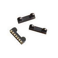
HSDL-3208-021 Lite-On Electronics, HSDL-3208-021 Datasheet - Page 3

HSDL-3208-021
Manufacturer Part Number
HSDL-3208-021
Description
Infrared Transceivers IR Transceiver 115Kb/s
Manufacturer
Lite-On Electronics
Type
TX/RXr
Datasheet
1.HSDL-3208-021.pdf
(23 pages)
Specifications of HSDL-3208-021
Wavelength
875 nm, 880 nm
Continual Data Transmission
115.2 Kbit/s
Radiant Intensity
8 mW/sr
Half Intensity Angle Degrees
30 deg to 60 deg
Pulse Width
4 us, 1.6 us
Maximum Rise Time
50 ns, 600 ns
Maximum Fall Time
50 ns, 600 ns
Led Supply Voltage
0 V to 6.5 V
Maximum Forward Current
50 mA
Operating Voltage
2.4 V to 3.6 V
Maximum Operating Temperature
+ 70 C
Minimum Operating Temperature
- 25 C
Dimensions
7.4 mm x 2.9 mm x 1.8 mm
Data Rate
115.2Kbps
Peak Wavelength
875/880nm
Angle Of Half Sensitivity
60/30°
Fall Time
600/50ns
Rise Time
600/50ns
Operating Supply Voltage (typ)
2.5/3.3V
Operating Supply Voltage (min)
2.4V
Operating Supply Voltage (max)
3.6V
Mounting
Surface Mount
Pin Count
7
Operating Temp Range
-25C to 70C
Operating Temperature Classification
Commercial
Idle Current, Typ @ 25° C
100µA
Link Range, Low Power
30cm
Operating Temperature
-25°C ~ 70°C
Orientation
Side View
Shutdown
*
Size
7mm x 2.8mm x 1.6mm
Standards
IrPHY 1.4
Supply Voltage
2.4 V ~ 3.6 V
Lead Free Status / RoHS Status
Lead free / RoHS Compliant
Available stocks
Company
Part Number
Manufacturer
Quantity
Price
Part Number:
HSDL-3208-021
Manufacturer:
AGILENT
Quantity:
20 000
3
TX Power Mode Switching
The transceiver is in default High TX Power Mode
upon powered on. User needs to apply the following
programming sequence to both SD and TXD inputs
to switch the module to Low TX Power Mode. Both
settings of High TX Power and Low TX Power Mode
can be achieved as follows:
Figure 3. High power mode selection timing diagram.
1. Set SD/Mode input to logic High.
2. TXD input should remain at logic Low.
3. After waiting for t
4. Ensure that TXD input remains low for t
5. SD input pulse width for mode selection should be
SD/MODE
Low. The High to Low negative edge transition will
determine the TX Power Mode.
The transmitter is now in High mode.
> 50 ns.
TXD
50%
t
S
s
25 ns, set SD/Mode to logic
50%
t
H
50%
V
V
IH
IL
V
IL
H
100 ns.
SD/MODE
Figure 4. Low power mode selection timing diagram.
1. Set SD/Mode input to logic High.
2. After SD/Mode input remains High at > 25 ns, set
3. Then set SD/Mode to logic Low. The High to Low
4. After waiting for t
5. SD input pulse width for mode selection should be
TXD input to logic High, wait t
of TXD rising edge until 50% of SD falling edge).
negative edge transition will determine the TX
Power Mode.
logic Low.
> 50 ns.
TXD
50%
t
S
H
100 ns, set the TXD input to
50%
t
H
50%
V
V
IH
IL
s
25 ns (from 50%
V
V
IL
IH


