KIT34844AEPEVBE Freescale Semiconductor, KIT34844AEPEVBE Datasheet - Page 17
KIT34844AEPEVBE
Manufacturer Part Number
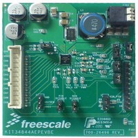
KIT34844AEPEVBE
Description
LED Lighting Development Kits IC, 10 CHANNEL LED BACKLIGHT
Manufacturer
Freescale Semiconductor
Datasheet
1.MC34844AEP.pdf
(62 pages)
Specifications of KIT34844AEPEVBE
Supply Voltage
12 V
Supply Current
2 uA
For Use With/related Products
34844A
Lead Free Status / RoHS Status
Lead free / RoHS Compliant


BOOST
synchronous mode and integrates a 2.5 A FET. An integrated
sense circuit is used to sense the voltage at the LED current
mirror inputs and automatically sets the boost output voltage
(DHC) to the minimum voltage needed to keep all LEDs
biased with the required current. The DHC is designed to
operate under specific pulse width conditions in the LED
drivers. It operates for pulse widths higher than 4.0 μs
circuit will not operate and the voltage across the LED drivers
will increase to a value given by the OVP minus the total LED
voltage in the LED string. Therefore it is imperative to select
the proper OVP level to minimize power dissipation.
the I
present, the OVP can be controlled by a resistor divider
connected from VOUT to GND with its mid point tied to A0/
SEN pin (threshold = 6.5 V). During an OVP condition, the
output voltage will go to the OVP level which is programmed
via the I
pin, or by a zener diode. The formulas to calculate the
hardware OVP using any of the two methods are as follows:
A0/SEN
The integrated boost converter operates in non-
If the pulse widths are shorter than specified, the DHC
The OVP can be set from 11 to 62 V, ~4.0 V spaced, using
FUNCTIONAL DESCRIPTION
FUNCTIONAL INTERNAL BLOCK DESCRIPTION
17
OVP = 6.5 V [(R
34844
2
Table 5. Operation Current Consumption Modes
C interface (OVP Register). If I
2
Method 1
C interface or settled by a resistor divider on A0/SEN
V
OUT
SM Bus
Manual
Mode
I
R LOWER
R UPPER
2
C
UPPER
/ R
LOWER
) + 1] + (100E-6 x R
EN Pin
High
High
High
Low
Low
Low
Low
Low
A0/SEN
2
C capability is not
UPPER
OVP = V
Method 2
SCK/SDA Pins
)
Low (> 27 ms)
ZENER2
Active
Active
V ZENER2
Low
Low
X
X
X
+ 6.5 V
I
2
C Bit Command
SETI2C bit = 1
CLRI2C bit = 0
SETI2C bit = 1
CLRI2C bit = 0
SETI2C bit = 1
CLRI2C bit = 0
HARDWARE OVP:
LED voltage over the whole temperature range. A good
practice is to set it 5.0 V or so above the max LED voltage.
Protection (OCP) and has a user programmable Over-
voltage Protection (OVP).
the OCP condition remains for more than 10 ms then the
device turns off the LED Drivers, the Boost goes to Sleep
mode and the output FAULT pin goes into high-impedance.
The device can only be restarted by recycling the enable or
creating a Power On Reset (POR).
(BST[1:0]) only after the IC is powered up and before the
boost circuit is turned ON for the first time (PWM pin low to
high). This sequence avoids boost frequency to be changed
inadvertently during operation. The first I
wait for 5.0 ms after the part is turned ON, in order to allow
sufficient time for the device power up sequence to be
completed.
amplifier with indefinite hold time capability, to enable
immediate LED on cycles after extended off times. During
extended off times, the external LEDs cool down from their
normal quiescent operating temperature and thereby
experience a forward voltage change, typically an increase in
the forward voltage. This change can be significant for
applications with a large number of series LEDs in a string
operating at high current. If the boost controller did not track
this increased change, the potential on the LED drivers would
saturate for a few cycles once the LED channels are re-
enabled.
EN bit = X
EN bit = 0
EN bit = 1
EN bit = X
EN bit = 0
EN bit = 1
The OVP value should be set to greater than the maximum
The boost converter also features internal Over-current
The OCP operates on a cycle by cycle basis. However, if
The user can program the boost frequency by I
The boost controller has an integral track and hold
N/A
N/A
Current Consumption
I
2
Operational
Operational
C Low Power
Operational
(Shutdown)
Shutdown
Shutdown
Analog Integrated Circuit Device Data
Mode
Sleep
Sleep
Freescale Semiconductor
2
C command has to
Part Doesn’t
Comments
Wake-up
2
C
Related parts for KIT34844AEPEVBE
Image
Part Number
Description
Manufacturer
Datasheet
Request
R

Part Number:
Description:
Manufacturer:
Freescale Semiconductor, Inc
Datasheet:
Part Number:
Description:
Manufacturer:
Freescale Semiconductor, Inc
Datasheet:
Part Number:
Description:
Manufacturer:
Freescale Semiconductor, Inc
Datasheet:
Part Number:
Description:
Manufacturer:
Freescale Semiconductor, Inc
Datasheet:
Part Number:
Description:
Manufacturer:
Freescale Semiconductor, Inc
Datasheet:
Part Number:
Description:
Manufacturer:
Freescale Semiconductor, Inc
Datasheet:
Part Number:
Description:
Manufacturer:
Freescale Semiconductor, Inc
Datasheet:
Part Number:
Description:
Manufacturer:
Freescale Semiconductor, Inc
Datasheet:
Part Number:
Description:
Manufacturer:
Freescale Semiconductor, Inc
Datasheet:
Part Number:
Description:
Manufacturer:
Freescale Semiconductor, Inc
Datasheet:
Part Number:
Description:
Manufacturer:
Freescale Semiconductor, Inc
Datasheet:
Part Number:
Description:
Manufacturer:
Freescale Semiconductor, Inc
Datasheet:
Part Number:
Description:
Manufacturer:
Freescale Semiconductor, Inc
Datasheet:
Part Number:
Description:
Manufacturer:
Freescale Semiconductor, Inc
Datasheet:
Part Number:
Description:
Manufacturer:
Freescale Semiconductor, Inc
Datasheet: