KIT34844AEPEVBE Freescale Semiconductor, KIT34844AEPEVBE Datasheet - Page 47
KIT34844AEPEVBE
Manufacturer Part Number
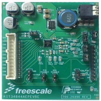
KIT34844AEPEVBE
Description
LED Lighting Development Kits IC, 10 CHANNEL LED BACKLIGHT
Manufacturer
Freescale Semiconductor
Datasheet
1.MC34844AEP.pdf
(62 pages)
Specifications of KIT34844AEPEVBE
Supply Voltage
12 V
Supply Current
2 uA
For Use With/related Products
34844A
Lead Free Status / RoHS Status
Lead free / RoHS Compliant


DISABLING LED CHANNELS
the 10 channels separately by writing the corresponding
CHENx bit on Registers 08 and 09 thru I2C.
feedback circuit of the LED drivers, this shouldn’t be used on
any channel that shuts down either because an open LED
channel condition or because is was previously POWER
OFF. This could cause instability issues since the voltage on
this open LED driver is not substantially above the DHC
regulation voltage (0.75 V typ) and may interfere with the
operation of the dynamic headroom control (DHC) which can
lead to erratic output voltage regulation
FAIL PIN
that particular LED channel will be close to ground and the
LED open failure is detected. When this happens, a failure is
registered, the FAIL pin is set to its high-impedance stage,
and the channel is shut down.
complete power on reset is applied.
cleared by cycling the clear fail bit (CLRFAIL bit = 0 - 1 - 0).
This allows the user to waive any known failure and set the
device for being able to detect any other failure during
operation.
that the failure is because of an over-current in the Boost.
Since this is a critical failure the only way to clear it is by
releasing the part from the over-current condition and then
shutdown the part (Refer to
be reset by removing the failure and re-enabling the device
thru the EN pin.
OPTICAL AND TEMPERATURE CONTROL LOOP
control.
adjusted depending on the temperature of the LEDs.
closed loop backlight control, where the brightness of the
backlight is maintained at a required level by adjusting the
light output, until the desired level is achieved, or with
ambient light control, where the backlight brightness
increases as ambient light increases.
the PIN and NIN pins. Each pin supports a 0 V to V
(2.048 V typ.) input range which affects the current through
the LEDs. The PIN pin increases current as the voltage rises
from 0 to V
rises from 0 - V
ISET pin if the part is configured to use PIN+NIN control loop
Analog Integrated Circuit Device Data
Freescale Semiconductor
The 34844A allows the user to enable and disable each of
Since the enable and disable functions reconnects the
If a LED fails open in any of the LED strings, the voltage in
The FAIL pin cannot be cleared for manual mode unless a
However for I
If the fail pin cannot be cleared by software then it indicates
If I
The 34844A supports both optical and temperature loop
For temperature loop control, the LED brightness can be
For optical loop control, the 34844A supports both optical
Both temperature and optical loops are supported through
A 6.98 kohm resistor or higher value must be used at the
2
C communication is not present, FAIL condition should
SET
. The NIN pin reduces current as the voltage
SET
2
C/SMBUS mode, the FAIL pin can be
.
Table
12)
SET
functionality, the 80 mA maximum current is achieved at the
higher allowed level of PIN/NIN pins, ensuring the maximum
current of the LED Drivers are not exceeded.
by I
pins high (>2.2 V). The LED Driver maximum current is set to
80 mA by using a 3.48 kohm resistor at the ISET pin.
correspodingly.
LED FAILURE PROTECTION
Open LED Protection
that channel will be pulled close to zero, which will cause the
channel to be disabled. As a result, the boost output voltage
will go to the OVP level and then come down to the regulation
level to continue powering the rest of the LED strings.
Short LED Protection
continue to operate without interruption. However, if the
shorted LED happens to be in the LED string with the highest
forward voltage, the DHC circuit will automatically regulate
the output voltage with respect to the new highest LED
voltage. If more LEDs are shorted in the same LED string, it
may cause excessive power dissipation in the channel which
may cause the OTT circuit to trip which will completely
shutdown the device.
OVER-TEMPERATURE PROTECTION
measures die temperature. If the IC temperature exceeds the
OTT threshold, the IC will turn off all power sources inside the
IC (LED drivers, boost and internal regulators) until the
temperature falls below the falling OTT threshold. Once it
comes back on, it will operate with the default configuration
(refer to
SERIAL INTERFACE CONTROL
standard (100 kHz) or fast (400 kHz) modes.
allow more than 2 devices in the system. The A0/SEN pin
should be held low on all chips expect the one to be
addressed, where it is taken HIGH.
The optical and temperature control loop can be disabled
VPIN and VNIN is the voltage applied on PIN and NIN pins
For ISINK formula please refer to
If LED fails open in any of the LED strings, the voltage in
If an LED shorted in any of the LED strings, the device will
The 34844A has an on-chip temperature sensor that
The 34844A uses an I
The A0/SEN pin can be used an address select pin to
2
C setting bits (PINEN & NINEN), or by tying PIN and NIN
Table
IDIM A
Current on LED Channel (PIN+NIN mode)
IDIM A
Current on LED Channel (NIN mode)
[ ]
Current on LED Channel (PIN mode)
14).
FUNCTIONAL INTERNAL BLOCK DESCRIPTION
IDIM A
[ ]
=
ISINK A
=
[ ]
ISINK A
[ ]
=
2
C interface capable of operating in
ISINK A
×
[ ]
(
------------------------------------------------------------------------- -
VSET
×
[ ]
(
----------------------------------------------------
FUNCTIONAL DESCRIPTION
VSET VNIN
×
+
VPIN V
----------------------- -
Equation
VPIN VNIN
–
2
2
2
[ ]
–
) V
[ ]
1.
) V
[ ]
34844A
Eqn. 10
Eqn. 8
Eqn. 9
47
Related parts for KIT34844AEPEVBE
Image
Part Number
Description
Manufacturer
Datasheet
Request
R

Part Number:
Description:
Manufacturer:
Freescale Semiconductor, Inc
Datasheet:
Part Number:
Description:
Manufacturer:
Freescale Semiconductor, Inc
Datasheet:
Part Number:
Description:
Manufacturer:
Freescale Semiconductor, Inc
Datasheet:
Part Number:
Description:
Manufacturer:
Freescale Semiconductor, Inc
Datasheet:
Part Number:
Description:
Manufacturer:
Freescale Semiconductor, Inc
Datasheet:
Part Number:
Description:
Manufacturer:
Freescale Semiconductor, Inc
Datasheet:
Part Number:
Description:
Manufacturer:
Freescale Semiconductor, Inc
Datasheet:
Part Number:
Description:
Manufacturer:
Freescale Semiconductor, Inc
Datasheet:
Part Number:
Description:
Manufacturer:
Freescale Semiconductor, Inc
Datasheet:
Part Number:
Description:
Manufacturer:
Freescale Semiconductor, Inc
Datasheet:
Part Number:
Description:
Manufacturer:
Freescale Semiconductor, Inc
Datasheet:
Part Number:
Description:
Manufacturer:
Freescale Semiconductor, Inc
Datasheet:
Part Number:
Description:
Manufacturer:
Freescale Semiconductor, Inc
Datasheet:
Part Number:
Description:
Manufacturer:
Freescale Semiconductor, Inc
Datasheet:
Part Number:
Description:
Manufacturer:
Freescale Semiconductor, Inc
Datasheet: