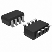
AD5273BRJZ1-REEL7 Analog Devices Inc, AD5273BRJZ1-REEL7 Datasheet

AD5273BRJZ1-REEL7
Specifications of AD5273BRJZ1-REEL7
Available stocks
Related parts for AD5273BRJZ1-REEL7
AD5273BRJZ1-REEL7 Summary of contents
Page 1
FEATURES 64 positions One-time programmable (OTP) 1 set-and-forget Resistance setting—low cost alternative over EEMEM Unlimited adjustments prior to OTP activation 1 kΩ, 10 kΩ, 50 kΩ, 100 kΩ end-to-end terminal resistance Compact 8-lead SOT-23 standard package Ultralow power ...
Page 2
AD5273 TABLE OF CONTENTS Features .............................................................................................. 1 Applications ....................................................................................... 1 General Description ......................................................................... 1 Functional Block Diagram .............................................................. 1 Revision History ............................................................................... 2 Specifications ..................................................................................... 4 Absolute Maximum Ratings ............................................................ 6 ESD Caution .................................................................................. 6 Pin Configuration and Function Descriptions ...
Page 3
A to Rev. B Changes to Features .......................................................................... 1 Changes to Applications ................................................................... 1 Changes to Specifications ................................................................. 2 Changes to Absolute Maximum Ratings ........................................ 4 Changes to Pin Function Descriptions ........................................... 5 Changes to TPC 7, TPC 8, ...
Page 4
AD5273 SPECIFICATIONS < −40°C < Table 1. Parameter DC CHARACTERISTICS—RHEOSTAT MODE Resolution 2 Resistor Differential Nonlinearity 10 kΩ, 50 kΩ, 100 ...
Page 5
Parameter POWER SUPPLIES Power Supply Range 8, 9 OTP Power Supply Supply Current 8, 10,11 OTP Supply Current 12 Power Dissipation Power Supply Sensitivity DYNAMIC CHARACTERISTICS 7, 13, 14 Bandwidth, −3 dB Total Harmonic Distortion Adjustment Settling Time Power-Up Settling ...
Page 6
AD5273 ABSOLUTE MAXIMUM RATINGS T = 25°C, unless otherwise noted. A Table 2. Parameter V to GND GND Maximum Current Pulsed Continuous (R ...
Page 7
PIN CONFIGURATION AND FUNCTION DESCRIPTIONS Table 3. Pin Function Descriptions Pin No. Mnemonic Description 1 W Wiper Terminal W. GND ≤ Positive Power Supply. Specified for nonOTP operation from 2 5.5 V. For OTP programming, ...
Page 8
AD5273 TYPICAL PERFORMANCE CHARACTERISTICS 0.5 0 0.1 –0 –0.3 –0 CODE (Decimal) Figure 3. R vs. Code vs. Supply Voltages INL 0.25 0.15 0.05 –0. ...
Page 9
SUPPLY VOLTAGE (V) Figure 9. INL vs. Supply Voltage 0.4 0.3 0.2 0.1 0 –0 SUPPLY VOLTAGE (V) Figure 10. R vs. Supply Voltage ...
Page 10
AD5273 500 400 300 1kΩ 200 10kΩ 100 0 50kΩ –100 100kΩ –200 –300 CODE (Decimal) Figure 15. Rheostat Mode Tempco (∆ 1kΩ 10kΩ –10 50kΩ 100kΩ –20 –30 –40 ...
Page 11
FREQUENCY (Hz) Figure 21. −3 dB Bandwidth – 25°C A CODE = 0x20 V = 2.5V ...
Page 12
AD5273 1kΩ 0.1 0. CODE (Decimal) Figure 27. I vs. Code WB_MAX SCL t 1 SDA OPEN 25° ...
Page 13
THEORY OF OPERATION The AD5273 is a one-time programmable (OTP), set-and-forget, 6-bit digital potentiometer. The AD5273 allows unlimited 6-bit adjustments prior to the OTP. OTP technology is a proven cost- effective alternative over EEMEM in one-time memory programming applications. The ...
Page 14
AD5273 VARIABLE RESISTANCE AND VOLTAGE FOR RHEOSTAT MODE If only the W-to-B or W-to-A terminals are used as variable resistors, the unused terminal can be opened or shorted with W. This operation is called rheostat mode (see ...
Page 15
Unlike rheostat mode where the absolute tolerance is high, potentiometer mode yields an almost ratiometric function of D/63 with a relatively small error contributed by the R Therefore, the tolerance effect is almost cancelled. Although the step resistor ...
Page 16
AD5273 CONTROLLING THE AD5273 To control the AD5273, users can program the device with either computer software or with external I SOFTWARE PROGRAMMING Because of the OTP feature, users can program the AD5273 in the factory before shipping it to ...
Page 17
I C CONTROLLER PROGRAMMING Write Bit Patterns 0 SCL SDA START BY FRAME 1 MASTER SLAVE ADDRESS BYTE 0 SCL SDA START BY FRAME 1 MASTER SLAVE ...
Page 18
AD5273 4. When all data bits have been read or written, a stop con- dition is established by the master. A stop condition is defined as a low-to-high transition on the SDA line while SCL is high. In write mode, ...
Page 19
APPLICATIONS INFORMATION DAC It is common to buffer the output of the digital potentiometer as a DAC. The buffer minimizes the load dependence and delivers higher current to the load, if needed AD5273 ...
Page 20
AD5273 Depending on the op amp GBP, reducing the feedback resistor may extend the zero’s frequency far enough to overcome the problem. A better approach is to include a compensation capacitor, C2, to cancel the effect caused by C1. Optimum ...
Page 21
EVALUATION BOARD 10mF 10kΩ 10kΩ GND 4 8 0.1µF SCL 7 SCL AD5170 6 5 SDA REF V REF A JP1 JP7 ...
Page 22
... INDICATOR 0.15 MAX ORDERING GUIDE Model R (kΩ) Temperature Range AB AD5273BRJ1-R2 1 −40°C to +105°C AD5273BRJ1-REEL7 1 −40°C to +105°C 1 AD5273BRJZ1-REEL7 1 −40°C to +105°C AD5273BRJ10-R2 10 −40°C to +105°C AD5273BRJ10-REEL7 10 −40°C to +105°C 1 AD5273BRJZ10-REEL7 10 −40°C to +105°C AD5273BRJ50-R2 50 − ...
Page 23
NOTES Rev Page AD5273 ...
Page 24
AD5273 NOTES 2 Purchase of licensed I C components of Analog Devices or one of its sublicensed Associated Companies conveys a license for the purchaser under the Philips I 2 Rights to use these components system, ...


