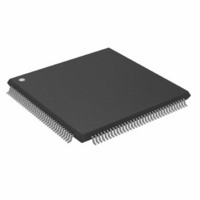
ADSP-2191MBSTZ-140 Analog Devices Inc, ADSP-2191MBSTZ-140 Datasheet - Page 14

ADSP-2191MBSTZ-140
Manufacturer Part Number
ADSP-2191MBSTZ-140
Description
IC,DSP,16-BIT,CMOS,QFP,144PIN,PLASTIC
Manufacturer
Analog Devices Inc
Series
ADSP-21xxr
Type
Fixed Pointr
Specifications of ADSP-2191MBSTZ-140
Interface
Host Interface, SPI, SSP, UART
Clock Rate
140MHz
Non-volatile Memory
External
On-chip Ram
160kB
Voltage - I/o
3.00V, 3.30V
Voltage - Core
2.50V
Operating Temperature
-40°C ~ 85°C
Mounting Type
Surface Mount
Package / Case
144-LQFP
Device Core Size
16b
Clock Freq (max)
140MHz
Mips
140
Device Input Clock Speed
140MHz
Ram Size
160KB
Operating Supply Voltage (typ)
2.5/3.3V
Operating Supply Voltage (min)
2.37/2.97V
Operating Supply Voltage (max)
2.63/3.6V
Operating Temp Range
-40C to 85C
Operating Temperature Classification
Industrial
Mounting
Surface Mount
Pin Count
144
Package Type
LQFP
Lead Free Status / RoHS Status
Lead free / RoHS Compliant
Lead Free Status / RoHS Status
Lead free / RoHS Compliant
Other names
ADSP-2191MBSTZ140
Available stocks
Company
Part Number
Manufacturer
Quantity
Price
Company:
Part Number:
ADSP-2191MBSTZ-140
Manufacturer:
MAXIM
Quantity:
101
Company:
Part Number:
ADSP-2191MBSTZ-140
Manufacturer:
Analog Devices Inc
Quantity:
10 000
ADSP-2191M
In addition to the software and hardware development tools
available from Analog Devices, third parties provide a wide range
of tools supporting the ADSP-219x processor family. Hardware
tools include ADSP-219x PC plug-in cards. Third party software
tools include DSP libraries, real-time operating systems, and
block diagram design tools.
Designing an Emulator-Compatible DSP Board
(Target)
The White Mountain DSP (Product Line of Analog Devices,
Inc.) family of emulators are tools that every DSP developer
needs to test and debug hardware and software systems. Analog
Devices has supplied an IEEE 1149.1 JTAG Test Access Port
(TAP) on each JTAG DSP. The emulator uses the TAP to access
the internal features of the DSP, allowing the developer to load
code, set breakpoints, observe variables, observe memory, and
examine registers. The DSP must be halted to send data and
commands, but once an operation has been completed by the
emulator, the DSP system is set running at full speed with no
impact on system timing.
To use these emulators, the target’s design must include the
interface between an Analog Devices JTAG DSP and the
emulation header on a custom DSP target board.
Target Board Header
The emulator interface to an Analog Devices JTAG DSP is a
14-pin header, as shown in
this header on the target board in order to communicate with the
emulator. The interface consists of a standard dual row 0.025"
square post header, set on 0.1"
post length of 0.235". Pin 3 is the key position used to prevent
the pod from being inserted backwards. This pin must be clipped
on the target board.
Also, the clearance (length, width, and height) around the header
must be considered. Leave a clearance of at least 0.15" and 0.10"
around the length and width of the header, and reserve a height
clearance to attach and detach the pod connector.
Equipped Analog Devices DSP (Jumpers in Place)
Figure 4. JTAG Target Board Connector for JTAG
KEY (NO PIN)
BTRST
BTMS
BTCK
BTDI
GND
GND
Figure
11
13
1
3
5
7
9
TOP VIEW
0.1" spacing, with a minimum
4. The customer must supply
14
10
12
2
4
6
8
TRST
TDI
TDO
EMU
GND
TMS
TCK
–14–
As can be seen in
header. There are the standard JTAG signals TMS, TCK, TDI,
TDO, TRST, and EMU used for emulation purposes (via an
emulator). There are also secondary JTAG signals BTMS,
BTCK, BTDI, and BTRST that are optionally used for
board-level (boundary scan) testing.
When the emulator is not connected to this header, place jumpers
across BTMS, BTCK, BTRST, and BTDI as shown in
This holds the JTAG signals in the correct state to allow the DSP
to run free. Remove all the jumpers when connecting the
emulator to the JTAG header.
JTAG Emulator Pod Connector
Figure 6
14-pin target end.
board header. The keep-out area allows the pod connector to
properly seat onto the target board header. This board area
should contain no components (chips, resistors, capacitors, etc.).
The dimensions are referenced to the center of the 0.25" square
post pin.
Figure 5. JTAG Target Board Connector with No Local
Boundary Scan
Figure 6. JTAG Pod Connector Dimensions
details the dimensions of the JTAG pod connector at the
0.64"
KEY (NO PIN)
Figure
Figure 7
BTRST
0.88"
BTMS
BTCK
BTDI
GND
GND
4, there are two sets of signals on the
displays the keep-out area for a target
11
13
1
3
5
7
9
TOP VIEW
0.24"
14
10
12
2
4
6
8
EMU
GND
TCK
TRST
TDI
TDO
TMS
Figure
REV. A
5.


