MT9D131C12STC Aptina LLC, MT9D131C12STC Datasheet - Page 12
MT9D131C12STC
Manufacturer Part Number
MT9D131C12STC
Description
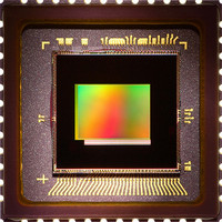
SENSOR IMAGE 2MP CMOS 48-CLCC
Manufacturer
Aptina LLC
Type
CMOS Imagingr
Specifications of MT9D131C12STC
Pixel Size
2.8µm x 2.8µm
Active Pixel Array
1600H x 1200V
Frames Per Second
15
Voltage - Supply
2.5 V ~ 3.1 V
Package / Case
48-CLCC
Sensor Image Color Type
Color
Sensor Image Size
1600x1200Pixels
Operating Supply Voltage (min)
1.7/2.5V
Operating Supply Voltage (typ)
1.8/2.8V
Operating Supply Voltage (max)
1.95/3.1V
Operating Temp Range
-30C to 70C
Package Type
CLCC
Operating Temperature Classification
Commercial
Mounting
Surface Mount
Pin Count
48
Lead Free Status / RoHS Status
Lead free / RoHS Compliant
For Use With
557-1253 - KIT HEAD BOARD FOR MT9D131557-1248 - KIT DEV FOR MT9D131
Lead Free Status / RoHS Status
Compliant, Lead free / RoHS Compliant
Other names
557-1311
Available stocks
Company
Part Number
Manufacturer
Quantity
Price
Company:

Part Number:
MT9D131C12STC
Manufacturer:
VIKING
Quantity:
120 000
Part Number:
MT9D131C12STC
Manufacturer:
APTINA
Quantity:
20 000
Company:
Part Number:
MT9D131C12STCH ES
Manufacturer:
Aptina LLC
Quantity:
135


Auto Exposure
Preview Mode
Scene Evaluative Algorithm
Auto White Balance
Flicker Detection
PDF: 09005aef824c90ce/Source: 09005aef824c90d6
MT9D131_LDS_2.fm - Rev. B 3/07 EN
1. preview
2. scene evaluative
The auto exposure (AE) algorithm performs automatic adjustments of the image bright-
ness by controlling exposure time and analog gains of the sensor core as well as digital
gains applied to the image.
Two auto exposure algorithm modes are available:
Auto exposure is implemented by means of a firmware driver that analyzes image statis-
tics collected by exposure measurement engine, makes a decision and programs the
sensor core and color pipeline to achieve the desired exposure. The measurement
engine subdivides the image into 16 windows organized as a 4 x 4 grid.
This exposure mode is activated during preview or video capture. It relies on the expo-
sure measurement engine that tracks speed and amplitude of the change of the overall
luminance in the selected windows of the image.
The backlight compensation is achieved by weighting the luminance in the center of the
image higher than the luminance on the periphery. Other algorithm features include the
rejection of fast fluctuations in illumination (time averaging), control of speed of
response, and control of the sensitivity to the small changes. While the default settings
are adequate in most situations, the user can program target brightness, measurement
window, and other parameters described above.
A scene evaluative AE algorithm is available for use in snapshot mode. The algorithm
performs scene analysis and classification with respect to its brightness, contrast and
composure and then decides to increase, decrease or keep original exposure target. It
makes most difference for backlight and bright outdoor conditions.
The MT9D131 has a built-in auto white balance (AWB) algorithm designed to compen-
sate for the effects of changing spectra of the scene illumination on the quality of the
color rendition. This sophisticated algorithm consists of two major parts: a measure-
ment engine performing statistical analysis of the image and a driver performing the
selection of the optimal color correction matrix, digital, and sensor core analog gains.
While default settings of these algorithms are adequate in most situations, the user can
re-program base color correction matrices, place limits on color channel gains, and con-
trol the speed of both matrix and gain adjustments. Unlike simple white balancing algo-
rithms found in many PC cameras, the MT9D131 AWB does not require the presence of
gray or white elements in the image for good color rendition. The AWB does not attempt
to locate "brightest" or "grayest" element of the image but instead performs sophisti-
cated image analysis to differentiate between changes in predominant spectra of illumi-
nation and changes in predominant colors of the scene. While defaults are suitable for
most applications, a wide range of algorithm parameters can be overwritten by the user
using the serial interface.
Flicker occurs when the integration time is not an integer multiple of the period of the
light intensity. The automatic flicker detection block does not compensate for the
flicker, but rather avoids it by detecting the flicker frequency and adjusting the integra-
tion time. For integration times below the light intensity period (10ms for 50Hz environ-
ment), flicker cannot be avoided.
MT9D131: 1/3.2-Inch 2-Mp SOC Digital Image Sensor
12
Micron Technology, Inc., reserves the right to change products or specifications without notice.
Architecture Overview
©2006 Micron Technology, Inc. All rights reserved.
Preliminary
Related parts for MT9D131C12STC
Image
Part Number
Description
Manufacturer
Datasheet
Request
R

Part Number:
Description:
SENSOR IMAGE VGA COLOR CMOS PLCC
Manufacturer:
Aptina LLC
Datasheet:

Part Number:
Description:
IC SENSOR IMAGE COLOR 48CLCC
Manufacturer:
Aptina LLC
Datasheet:

Part Number:
Description:
SENSOR IMAGE 1.3MP CMOS 48-CLCC
Manufacturer:
Aptina LLC
Datasheet:

Part Number:
Description:
SENSOR IMAGE VGA MONO 52IBGA
Manufacturer:
Aptina LLC
Datasheet:

Part Number:
Description:
SENSOR IMAGE VGA COLOR 48CLCC
Manufacturer:
Aptina LLC
Datasheet:

Part Number:
Description:
SENSOR IMAGE COLOR CMOS 48-PLCC
Manufacturer:
Aptina LLC
Datasheet:

Part Number:
Description:
KIT HEAD BOARD FOR MT9P031
Manufacturer:
Aptina LLC
Datasheet:

Part Number:
Description:
KIT HEAD BOARD FOR MT9D131
Manufacturer:
Aptina LLC
Datasheet:

Part Number:
Description:
KIT HEAD BOARD FOR MT9P031
Manufacturer:
Aptina LLC
Datasheet:

Part Number:
Description:
KIT HEAD BOARD FOR MT9M032
Manufacturer:
Aptina LLC
Datasheet:

Part Number:
Description:
PARALLEL HEADBOARD FOR MT9M032
Manufacturer:
Aptina LLC
Datasheet:
Part Number:
Description:
SENSOR IMAGE VGA COLOR CMOS PLCC
Manufacturer:
Aptina LLC
Datasheet:
Part Number:
Description:
IC SENSOR IMAGE COLOR 48CLCC
Manufacturer:
Aptina LLC
Datasheet:
