SPB17N80C3 Infineon Technologies, SPB17N80C3 Datasheet - Page 3
SPB17N80C3
Manufacturer Part Number
SPB17N80C3
Description
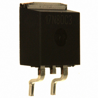
MOSFET N-CH 800V 17A D2PAK
Manufacturer
Infineon Technologies
Series
CoolMOS™r
Specifications of SPB17N80C3
Package / Case
D²Pak, TO-263 (2 leads + tab)
Fet Type
MOSFET N-Channel, Metal Oxide
Fet Feature
Standard
Rds On (max) @ Id, Vgs
290 mOhm @ 11A, 10V
Drain To Source Voltage (vdss)
800V
Current - Continuous Drain (id) @ 25° C
17A
Vgs(th) (max) @ Id
3.9V @ 1mA
Gate Charge (qg) @ Vgs
177nC @ 10V
Input Capacitance (ciss) @ Vds
2300pF @ 100V
Power - Max
227W
Mounting Type
Surface Mount
Minimum Operating Temperature
- 55 C
Configuration
Single
Transistor Polarity
N-Channel
Resistance Drain-source Rds (on)
0.29 Ohm @ 10 V
Drain-source Breakdown Voltage
800 V
Gate-source Breakdown Voltage
+/- 20 V
Continuous Drain Current
17 A
Power Dissipation
208000 mW
Maximum Operating Temperature
+ 150 C
Mounting Style
SMD/SMT
Continuous Drain Current Id
17A
Drain Source Voltage Vds
800V
On Resistance Rds(on)
290mohm
Rds(on) Test Voltage Vgs
10V
Threshold Voltage Vgs Typ
3V
Rohs Compliant
Yes
Fall Time
6 ns
Rise Time
15 ns
Lead Free Status / RoHS Status
Lead free / RoHS Compliant
Lead Free Status / RoHS Status
Lead free / RoHS Compliant, Lead free / RoHS Compliant
Other names
SP000013370
SPB17N80C3INTR
SPB17N80C3T
SPB17N80C3XT
SPB17N80C3XTINTR
SPB17N80C3XTINTR
SPB17N80C3INTR
SPB17N80C3T
SPB17N80C3XT
SPB17N80C3XTINTR
SPB17N80C3XTINTR
Available stocks
Company
Part Number
Manufacturer
Quantity
Price
Company:

Part Number:
SPB17N80C3
Manufacturer:
INFINEON
Quantity:
5 600
Company:
Part Number:
SPB17N80C3
Manufacturer:
INFINEON
Quantity:
30 000
Part Number:
SPB17N80C3
Manufacturer:
INFINEON/英飞凌
Quantity:
20 000


Rev. 2.3
1)
2)
3)
4)
is vertical without blown air
5)
6)
Parameter
Dynamic characteristics
Input capacitance
Output capacitance
Effective output capacitance, energy
related
Effective output capacitance, time
related
Turn-on delay time
Rise time
Turn-off delay time
Fall time
Gate Charge Characteristics
Gate to source charge
Gate to drain charge
Gate charge total
Gate plateau voltage
Reverse Diode
Diode forward voltage
Reverse recovery time
Reverse recovery charge
Peak reverse recovery current
J-STD20 and JESD22
Pulse width t
Repetitive avalanche causes additional power losses that can be calculated as P
Device on 40mm*40mm*1.5 epoxy PCB FR4 with 6cm2 (one layer, 70µm thick) copper area for drain connection. PCB
C
C
o(er)
o(tr)
is a fixed capacitance that gives the same charging time as C
5)
6)
is a fixed capacitance that gives the same stored energy as C
p
limited by T
j,max
Symbol Conditions
C
C
C
C
t
t
t
t
Q
Q
Q
V
V
t
Q
I
d(on)
r
d(off)
f
rr
rrm
plateau
SD
iss
oss
o(er)
o(tr)
gs
gd
g
rr
V
f =1 MHz
V
to 480 V
V
V
R
Tj = 125°C
V
V
V
T
V
di
page 3
j
GS
GS
DD
GS
DD
GS
GS
R
G
=25 °C
F
=400 V, I
/dt =100 A/µs
=4.7
=0 V, V
=0 V, V
=400 V,
=0/10 V, I
=640 V, I
=0 to 10 V
=0 V, I
F
DS
DS
=I
F
oss
=I
D
oss
S
=100 V,
=0 V
D
=17 A,
,
=17 A,
S
while V
while V
,
DS
DS
is rising from 0 to 80% V
AV
is rising from 0 to 80% V
min.
=E
-
-
-
-
-
-
-
-
-
-
-
-
-
-
-
-
AR
*f.
Values
2300
typ.
100
210
550
5.5
72
45
18
85
15
12
48
91
15
51
1
SPB17N80C3
max.
177
1.2
DSS.
-
-
-
-
-
-
-
-
-
-
-
-
-
-
DSS.
Unit
pF
ns
nC
V
V
ns
µC
A
2007-11-28
Related parts for SPB17N80C3
Image
Part Number
Description
Manufacturer
Datasheet
Request
R


Part Number:
Description:
Manufacturer:
Infineon Technologies AG
Datasheet:
Part Number:
Description:
Manufacturer:
Infineon Technologies AG
Datasheet:
Part Number:
Description:
Manufacturer:
Infineon Technologies AG
Datasheet:
Part Number:
Description:
Manufacturer:
Infineon Technologies AG
Datasheet:
Part Number:
Description:
Manufacturer:
Infineon Technologies AG
Datasheet:
Part Number:
Description:
Manufacturer:
Infineon Technologies AG
Datasheet:
Part Number:
Description:
Manufacturer:
Infineon Technologies AG
Datasheet:
Part Number:
Description:
16-bit microcontroller with 2x2 KByte RAM
Manufacturer:
Infineon Technologies AG
Datasheet:
Part Number:
Description:
NPN silicon RF transistor
Manufacturer:
Infineon Technologies AG
Datasheet:
Part Number:
Description:
NPN silicon RF transistor
Manufacturer:
Infineon Technologies AG
Datasheet:
Part Number:
Description:
NPN silicon RF transistor
Manufacturer:
Infineon Technologies AG
Datasheet:
Part Number:
Description:
NPN silicon RF transistor
Manufacturer:
Infineon Technologies AG
Datasheet:
Part Number:
Description:
Si-MMIC-amplifier in SIEGET 25-technologie
Manufacturer:
Infineon Technologies AG
Datasheet:
Part Number:
Description:
IGBT Power Module
Manufacturer:
Infineon Technologies AG
Datasheet: