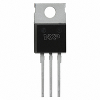
BUK9520-55,127 NXP Semiconductors, BUK9520-55,127 Datasheet - Page 5

BUK9520-55,127
Manufacturer Part Number
BUK9520-55,127
Description
MOSFET N-CH 55V 52A SOT78
Manufacturer
NXP Semiconductors
Series
TrenchMOS™r
Datasheet
1.BUK9520-55127.pdf
(8 pages)
Specifications of BUK9520-55,127
Fet Type
MOSFET N-Channel, Metal Oxide
Fet Feature
Logic Level Gate
Rds On (max) @ Id, Vgs
20 mOhm @ 25A, 5V
Drain To Source Voltage (vdss)
55V
Current - Continuous Drain (id) @ 25° C
52A
Vgs(th) (max) @ Id
2V @ 1mA
Input Capacitance (ciss) @ Vds
2400pF @ 25V
Power - Max
116W
Mounting Type
Through Hole
Package / Case
TO-220AB-3
Lead Free Status / RoHS Status
Lead free / RoHS Compliant
Gate Charge (qg) @ Vgs
-
Other names
934050400127
BUK9520-55
BUK9520-55
BUK9520-55
BUK9520-55
Philips Semiconductors
April 1998
TrenchMOS
Logic level FET
Fig.13. Typical turn-on gate-charge characteristics.
VGS/V
1E-01
1E-02
1E-03
1E-04
1E-05
1E-05
V
3.5
2.5
1.5
GS
.5
Fig.12. Typical capacitances, C
4
3
2
1
0
0.01
I
C = f(V
6
5
4
3
2
1
0
D
0
0
= f(Q
= f(V
Fig.11. Sub-threshold drain current.
G
GS)
DS
); conditions: I
0.5
); conditions: V
; conditions: T
0.1
10
2%
transistor
1
typ
D
1
1.5
20
= 50 A; parameter V
j
VDS = 14V
GS
= 25 ˚C; V
VDS/V
Sub-Threshold Conduction
= 0 V; f = 1 MHz
QG/nC
98%
2
iss
10
, C
30
DS
oss
= V
2.5
VDS = 44V
, C
GS
rss
100
.
DS
Coss
Crss
Ciss
40
3
5
VGS
0
IF/A
I
Fig.15. Normalised avalanche energy rating.
F
100
120
110
100
80
60
40
20
= f(V
90
80
70
60
50
40
30
20
10
0
0
0
Fig.14. Typical reverse diode current.
Fig.16. Avalanche energy test circuit.
20
W
WDSS%
W
SDS
DSS
DSS
0.2
40
); conditions: V
% = f(T
RGS
0.5 LI
60
0.4
Tj/C =
mb
80
); conditions: I
D
2
0.6
BV
VSDS/V
Tmb / C
100
175
GS
DSS
L
0.8
= 0 V; parameter T
VDS
120
BV
T.U.T.
Product specification
DSS
BUK9520-55
140
D
1
shunt
= 49 A
R 01
25
V
DD
160
-
+
1.2
Rev 1.100
-ID/100
180
VDD
1.4
j


