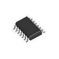
AU5783D NXP Semiconductors, AU5783D Datasheet - Page 6

AU5783D
Manufacturer Part Number
AU5783D
Description
RF Transceiver J1850/VPW XCVR
Manufacturer
NXP Semiconductors
Datasheet
1.AU5783D-T.pdf
(14 pages)
Specifications of AU5783D
Number Of Receivers
1
Number Of Transmitters
1
Operating Supply Voltage
5.5 V to 16 V
Mounting Style
SMD/SMT
Package / Case
SOT-108
Lead Free Status / RoHS Status
Lead free / RoHS Compliant
1. After power-on, the AU5783 enters standby mode since the input pins NSTB and 4X/LOOP are assumed to be floating. In standby mode the
2. RX outputs the bus state. If the bus level is below the receiver threshold (i.e., all transmitters passive), then RX will be high. Otherwise, if the
3. INH is turned off after a time-out period.
4. For entering the sleep mode (e.g., to deactivate INH), the “Go To Sleep” command needs to be applied. The “Go To Sleep” command is a
5. In standby and sleep mode, the detection of a wake-up condition (e.g., high level on BUS) will be signalled on the output RX.
6. The NSTB pin contains a weak pull down which is active in the normal, loop-back and high-speed modes but is disabled in the sleep mode.
Philips Semiconductors
Table 1. Control input summary
Z = Input connected to high impedance permitting it to float. Typically accomplished by turning off the output of a microcontroller.
X = Don’t care; The input may be at either logic level.
NOTES:
2001 Feb 15
J1850/VPW transceiver with supply control function
voltage regulator is enabled via the INH output, and therefore power is supplied to the microcontroller. When the microcontroller begins
operation it will normally set the control inputs NSTB high and 4X/LOOP to low state in order to start normal operation of the AU5783.
bus level is above the receiver threshold (i.e., at least one transmitter is active), then RX will be low.
high-to-low transition on the NSTB input. When the “Go To Sleep” command is present, the INH flag is deactivated. This signal can be used
to turn-off the voltage regulator of an electronic module. After the voltage regulator is turned off the microcontroller is no longer supplied and
the NSTB input will be floating. The INH output will be set again upon detection of bus activity or occurrence of a local wake-up event.
To insure a logic 0 input if the microcontroller’s outputs are tri-stated or the microcontroller is not powered, a 100 k resistor between NSTB
and ground is suggested.
NSTB
1 –> 0
0 or Z
0 or Z
1
1
1
1
1
1
4X/LOOP
X
X
X
0
0
1
1
Z
Z
TX
1
0
1
0
1
0
X
0
X
normal operation
normal operation
4X transmit
4X transmit
loop-back
loop-back
standby (default state after power on),
Note 1, Note 6
go to sleep command, Note 4, Note 6
sleep, Note 4, Note 6
Mode
6
active
passive
active
passive
passive
passive
off
off
off
transmitter
Bus
high
float
high
float
float
float
float
float
float
BUS
low
bus state,
Note 2
low
bus state,
Note 2
low
high
bus state,
Note 5
bus state,
Note 5
bus state,
Note 5
RX (out)
Preliminary specification
AU5783
high
high
high
high
high
high
high
float, Note 3
float
INH


