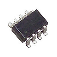
LTC2927ITS8#PBF Linear Technology, LTC2927ITS8#PBF Datasheet - Page 6

LTC2927ITS8#PBF
Manufacturer Part Number
LTC2927ITS8#PBF
Description
Manufacturer
Linear Technology
Datasheet
1.LTC2927ITS8PBF.pdf
(16 pages)
Specifications of LTC2927ITS8#PBF
Operating Temperature (max)
85C
Operating Temperature (min)
-40C
Pin Count
8
Mounting
Surface Mount
Package Type
TSOT-23
Case Length
2.9mm
Screening Level
Industrial
Lead Free Status / RoHS Status
Compliant
Available stocks
Company
Part Number
Manufacturer
Quantity
Price
APPLICATIO S I FOR ATIO
LTC2927
Power Supply Tracking and Sequencing
The LTC2927 handles a variety of power-up profi les to
satisfy the requirements of digital logic circuits including
FPGAs, PLDs, DSPs and microprocessors. These require-
ments fall into one of the four general categories illustrated
in Figures 1 to 4.
Some applications require that the potential difference
between two power supplies must never exceed a speci-
fi ed voltage. This requirement applies during power-up
and power-down as well as during steady-state operation,
often to prevent destructive latch-up in a dual supply
ASIC. Typically, this is achieved by ramping the supplies
up and down together (Figure 1). In other applications it
is desirable to have supplies ramp up and down with fi xed
voltage offsets between them (Figure 2) or to have them
ramp up and down ratiometrically (Figure 3).
Certain applications require one supply to come up after
another. For example, a system clock may need to start
6
1V/DIV
1V/DIV
Figure 3. Ratiometric Tracking
Figure 1. Coincident Tracking
U
10ms/DIV
10ms/DIV
U
W
2927 F01
2927 F03
U
MASTER
SLAVE1
SLAVE2
MASTER
SLAVE1
SLAVE2
before a block of logic. In this case, the supplies are se-
quenced as in Figure 4 where the 2.5V supply ramps up
after the 1.8V supply is completely powered.
Operation
The LTC2927 provides a simple solution to all of the
power supply tracking and sequencing profi les shown in
Figures 1 to 4. A single LTC2927 controls a single sup-
ply that tracks to a “master” signal. With two resistors,
a slave supply is confi gured to ramp up as a function of
the master signal. This master signal can be a separate
supply or it can be a ramp signal generated by tying the
RAMP pin to an external capacitor.
Tracking Cell
The LTC2927’s operation is based on the tracking cell
shown in Figure 5, which uses a proprietary wide-range
current mirror. The tracking cell shown in Figure 5 servos
the TRACK pin at 0.8V. The current supplied by the TRACK
1V/DIV
1V/DIV
Figure 4. Supply Sequencing
Figure 2. Offset Tracking
10ms/DIV
10ms/DIV
2927 F02
2927 F04
MASTER
SLAVE1
SLAVE2
MASTER
SLAVE1
SLAVE2
2927fb


