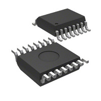
MIC74BQS Micrel Inc, MIC74BQS Datasheet - Page 15

MIC74BQS
Manufacturer Part Number
MIC74BQS
Description
IC I/O EXPANDER I2C 8B 16QSOP
Manufacturer
Micrel Inc
Series
-r
Datasheet
1.MIC74YQS.pdf
(18 pages)
Specifications of MIC74BQS
Interface
I²C, SMBus
Number Of I /o
8
Interrupt Output
Yes
Frequency - Clock
-
Voltage - Supply
2.7 V ~ 3.6 V
Operating Temperature
-40°C ~ 85°C
Mounting Type
Surface Mount
Package / Case
16-SSOP (0.154", 3.90mm Width)
Includes
-
Lead Free Status / Rohs Status
Contains lead / RoHS non-compliant
The act of reading STATUS clears it in preparation for
detecting future events. The status bits corresponding to
I/O’s configured as outputs or corresponding to P[7:4]
when in fan mode will not be set by state changes on
these pins. It is always good practice, however, for the
interrupt service routine to mask the value obtained
when reading STATUS to eliminate any bits, output or
otherwise, that are not of immediate concern. This will
help avoid problems if software changes are made in the
future.
The process for writing output data is straight-forward—
simply write the desired bit pattern to DATA. Special
precautions may be required, however, when changing
output data in an interrupt driven system. See the
discussion below under “Writing to the Data Register.”
Micrel, Inc.
October 2006
Figure 11: Interrupt Service Routine Using the ARA
Yes
response address
Read STATUS to
determine source
Interrupt Service
Return from ISR
Read alert
Interrupts
interrupt
pending
Routine
Sm set
MIC74
Sn set
Sx set
from
Is
Is
Is
Is
?
?
?
?
Yes
No
No
No
No
No
Yes
Yes
Yes
Service other devices
Service function m
Service function n
Service function x
15
Writing To The Data Register
Multiple software routines may use the various output
bits available on the MIC74 to control individual functions
such as power switches, LED’s, etc. These various
functions may be handled by independent software
routines which must manipulate individual output bits
without regard for other bits. Care must be taken to
insure that these various software routines do not
interfere with each other when modifying output data.
The recommended procedure for changing isolated
output bits is as follows:
A functionally equivalent alternative to this procedure is
to keep an image of the data register in software. Any
independent routines would make changes to this image
using the procedure above and then call a routine that
actually writes the new image to DATA. Interrupts would
be disabled briefly while DATA is being modified.
1. Read DATA
2. Set desired bits by ORing the value read from
3. Clear desired bits by ANDing the value read
4. Write the result back to DATA
Figure 12: Interrupt Service Routine Without ARA
DATA with an appropriate mask value
from DATA with an appropriate mask value
Return from ISR
STATUS
STATUS
Sm set
Polled
Sn set
Sx set
I.S.R.
Read
Is
Is
Is
Is
?
?
?
?
h
Yes
No
No
No
No
Yes
Yes
Yes
Service other devices
Service function m
Service function n
Service function x
M9999-101006
MIC74


