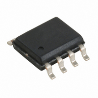
W40S01-04H Cypress Semiconductor Corp, W40S01-04H Datasheet - Page 8

W40S01-04H
Manufacturer Part Number
W40S01-04H
Description
IC CLK BUFF 18OUT SDRAM 48SSOP
Manufacturer
Cypress Semiconductor Corp
Type
Clock Bufferr
Datasheet
1.W40S01-04H.pdf
(11 pages)
Specifications of W40S01-04H
Input
Crystal or Other
Output
CMOS
Frequency - Max
133MHz
Voltage - Supply
3.135 V ~ 3.465 V
Operating Temperature
0°C ~ 70°C
Mounting Type
Surface Mount
Package / Case
48-SSOP
Frequency-max
133MHz
Lead Free Status / RoHS Status
Contains lead / RoHS non-compliant
Other names
428-1400
Available stocks
Company
Part Number
Manufacturer
Quantity
Price
Company:
Part Number:
W40S01-04H
Manufacturer:
CYPRESS
Quantity:
90
Part Number:
W40S01-04H
Manufacturer:
WORKS
Quantity:
20 000
Absolute Maximum Ratings
Stresses greater than those listed in this table may cause per-
manent damage to the device. These represent a stress rating
only. Operation of the device at these or any other conditions
DC Electrical Characteristics:
V
T
T
T
I
I
Logic Inputs (BUF_IN, OE, SCLOCK, SDATA)
V
V
I
I
Logic Outputs (SDRAM0:17)
V
V
I
I
Pin Capacitance/Inductance
C
C
L
Notes:
DD
DD Tristate
ILEAK
ILEAK
OL
OH
3.
4.
A
Parameter
IN
DD
STG
B
IL
IH
OL
OH
IN
OUT
Parameter
, V
OE, SCLOCK, and SDATA logic pins have a 250-k internal pull-up resistor (not CMOS level).
Outputs loaded by 6" 60 transmission lines with 20-pF capacitors.
IN
3.3V Supply Current
3.3V Supply Current in Three-state
Input Low Voltage
Input High Voltage
Input Leakage Current, BUF_IN
Input Leakage Current
Output Low Voltage
Output High Voltage
Output Low Current
Output High Current
Input Pin Capacitance (Except
BUF_IN)
Output Pin Capacitance
Input Pin Inductance
Voltage on any pin with respect to GND
Storage Temperature
Operating Temperature
Ambient Temperature under Bias
Description
[4]
T
[3]
A
= 0°C to +70°C, V
Description
BUF_IN = 100 MHz
BUF_IN = 100 MHz
I
I
V
V
OL
OH
OL
OH
DDQ3
Test Condition/
= 1 mA
= –1 mA
8
= 1.5V
Comments
= 1.5V
above those specified in the operating sections of this specifi-
cation is not implied. Maximum conditions for extended peri-
ods may affect reliability
= 3.3V ± 5%
GND–0.3
–0.5 to +7.0
–65 to +150
–55 to +125
0 to +70
Min.
–20
Rating
2.0
3.1
–5
70
65
Typ.
320
110
100
5
V
DDQ3
W40S01-04
Max.
185
160
0.8
+5
+5
50
5
6
7
Unit
+0.5
°C
°C
°C
V
Unit
mA
mA
mV
mA
mA
nH
µA
µA
pF
pF
V
V
V


