ADF4213BCP Analog Devices Inc, ADF4213BCP Datasheet - Page 9
ADF4213BCP
Manufacturer Part Number
ADF4213BCP
Description
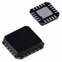
IC PLL FREQ SYNTHESIZER 20-LFCSP
Manufacturer
Analog Devices Inc
Type
Clock/Frequency Synthesizer (RF/IF)r
Datasheet
1.ADF4213BRU-REEL.pdf
(20 pages)
Specifications of ADF4213BCP
Rohs Status
RoHS non-compliant
Pll
Yes
Input
CMOS
Output
Clock
Number Of Circuits
1
Ratio - Input:output
3:1
Differential - Input:output
Yes/No
Frequency - Max
3GHz
Divider/multiplier
No/No
Voltage - Supply
2.7 V ~ 5.5 V
Operating Temperature
-40°C ~ 85°C
Mounting Type
Surface Mount
Package / Case
20-LFCSP
Frequency-max
3GHz
Available stocks
Company
Part Number
Manufacturer
Quantity
Price

Part Number:
ADF4213BCP
Manufacturer:
ADI/亚德诺
Quantity:
20 000


CIRCUIT DESCRIPTION
REFERENCE INPUT SECTION
The reference input stage is shown below in Figure 2. SW1 and
SW2 are normally-closed switches. SW3 is normally-open. When
power-down is initiated, SW3 is closed and SW1 and SW2 are
opened. This ensures that there is no loading of the REF
on power-down.
RF/IF INPUT STAGE
The RF/IF input stage is shown in Figure 3. It is followed by a
2-stage limiting amplifier to generate the CML (Current Mode
Logic) clock levels needed for the prescaler.
–100
–60
–70
–80
–90
–40
RF
RF
REF
IN
IN
IN
A
B
–20
GENERATOR
NC
POWER-DOWN
SW1
BIAS
CONTROL
NO
0
NC
TEMPERATURE – C
SW3
2k
SW2
20
100k
1.6V
NC = NO CONNECT
2k
40
BUFFER
60
AGND
AV
TO R COUNTER
V
V
DD
DD
P
= 5V
= 3V
80
100
IN
pin
ADF4210/ADF4211/ADF4212/ADF4213
PRESCALER (P/P + 1)
The dual modulus prescaler (P/P + 1), along with the A and
B counters, enables the large division ratio, N, to be realized
(N = PB + A). The dual-modulus prescaler, operating at CML
levels, takes the clock from the RF/IF input stage and divides
it down to a manageable frequency for the CMOS A and B
counters in the RF and If sections. The prescaler in both
sections is programmable. It can be set in software to 8/9, 16/17,
32/33, or 64/65. See Tables IV and VI. It is based on a syn-
chronous 4/5 core.
RF/IF A AND B COUNTERS
The A and B CMOS counters combine with the dual modulus
prescaler to allow a wide ranging division ratio in the PLL
feedback counter. The counters are specified to work when the
prescaler output is 200 MHz or less, when V
they will work with 250 MHz output from the prescaler. Thus,
with an RF input frequency of 2.5 GHz, a prescaler value of
16/17 is valid, but a value of 8/9 is not valid.
Pulse Swallow Function
The A and B counters, in conjunction with the dual modulus
prescaler make it possible to generate output frequencies which
are spaced only by the Reference Frequency divided by R. The
equation for the VCO frequency is as follows:
f
P
B
A
f
R
RF/IF COUNTER
The 15-bit RF/IF R counter allows the input reference fre-
quency to be divided down to product the input clock to the
phase frequency detector (PFD). Division ratios from 1 to
32767 are allowed.
VCO
REFIN
INPUT STAGE
= Output Frequency of external voltage controlled
= Preset modulus of dual modulus prescaler (8/9,
= Preset Divide Ratio of binary 13-bit counter
= Preset Divide Ratio of binary 6-bit A counter
= External reference frequency oscillator.
= Preset divide ratio of binary 15-bit programmable refer-
FROM RF
oscillator (VCO).
16/17, etc.).
(3 to 8191).
(0 to 63).
ence counter (1 to 32767).
f
VCO
MODULUS
CONTROL
= [(P × B) + A] × f
N = BP + A
PRESCALER
P/P + 1
LOAD
LOAD
COUNTER
COUNTER
13-BIT B-
REFIN
5-BIT A-
DD
/R
= 5 V. Typically,
TO PFD
Related parts for ADF4213BCP
Image
Part Number
Description
Manufacturer
Datasheet
Request
R

Part Number:
Description:
±1.7g Dual-Axis IMEMS Accelerometer Evaluation Board
Manufacturer:
Analog Devices Inc
Datasheet:

Part Number:
Description:
Inertial Sensor Evaluation System
Manufacturer:
Analog Devices Inc
Datasheet:
Part Number:
Description:
Manufacturer:
Analog Devices Inc
Datasheet:
Part Number:
Description:
Manufacturer:
Analog Devices Inc
Datasheet:
Part Number:
Description:
Manufacturer:
Analog Devices Inc
Datasheet:
Part Number:
Description:
Manufacturer:
Analog Devices Inc
Datasheet:
Part Number:
Description:
Manufacturer:
Analog Devices Inc
Datasheet:
Part Number:
Description:
Manufacturer:
Analog Devices Inc
Datasheet:
Part Number:
Description:
Manufacturer:
Analog Devices Inc
Datasheet:
Part Number:
Description:
Manufacturer:
Analog Devices Inc
Datasheet:
Part Number:
Description:
Manufacturer:
Analog Devices Inc
Datasheet:
Part Number:
Description:
Manufacturer:
Analog Devices Inc
Datasheet:
Part Number:
Description:
Manufacturer:
Analog Devices Inc
Datasheet: