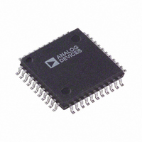
AD2S1200WSTZ Analog Devices Inc, AD2S1200WSTZ Datasheet - Page 8

AD2S1200WSTZ
Manufacturer Part Number
AD2S1200WSTZ
Description
IC R/D CONV W/REF OSCIL 44-LQFP
Manufacturer
Analog Devices Inc
Type
R/D Converterr
Datasheet
1.AD2S1200.pdf
(24 pages)
Specifications of AD2S1200WSTZ
Resolution (bits)
12 b
Data Interface
Serial, Parallel
Voltage Supply Source
Analog and Digital
Voltage - Supply
4.75 V ~ 5.25 V
Operating Temperature
-40°C ~ 125°C
Mounting Type
Surface Mount
Package / Case
44-LQFP
Input Channel Type
Differential
Supply Voltage Range - Analog
4.75V To 5.25V
Supply Voltage Range - Digital
4.75V To 5.25V
Lead Free Status / RoHS Status
Lead free / RoHS Compliant
For Use With
EVAL-AD2S1200CBZ - BOARD EVAL FOR AD2S1200
Sampling Rate (per Second)
-
Lead Free Status / RoHS Status
Lead free / RoHS Compliant, Lead free / RoHS Compliant
Available stocks
Company
Part Number
Manufacturer
Quantity
Price
Company:
Part Number:
AD2S1200WSTZ
Manufacturer:
Analog Devices Inc
Quantity:
135
Company:
Part Number:
AD2S1200WSTZ
Manufacturer:
ADI
Quantity:
276
Company:
Part Number:
AD2S1200WSTZ
Manufacturer:
Analog Devices Inc
Quantity:
10 000
AD2S1200
RESOLVER FORMAT SIGNALS
A resolver is a rotating transformer typically with a primary
winding on the rotor and two secondary windings on the stator.
In the case of a variable reluctance resolver, there are no wind-
ings on the rotor as shown in Figure 3. The primary winding is
on the stator as well as the secondary windings, but the saliency
in the rotor design provides the sinusoidal variation in the
secondary coupling with the angular position. Either way, the
resolver output voltages (S3–S1, S2–S4) will have the same
equations as shown in Equation 1.
θ
S
S
Sin
E
3
2
0
=
−
−
ω
=
Shaft
S
S
t
1
Rotor
4
=
=
=
V
Rotor
(A) CLASSICAL RESOLVER
r
E
E
Angle
θ
V
= V
0
b
0
Excitation
R1
S1
Sin
= V
p
Sin
Equation 1.
× Sin(ϖt)
Excitation
s
ω
ω
× Sin(ϖt) × Sin(θ)
t
t
×
×
R2
Sin
Cos
Amplitude
θ
θ
S3
Frequency
V
Figure 3. Classical Resolver vs. Variable Reluctance Resolver
a
= V
S2
S4
s
× Sin(ϖt) × Cos(θ)
Rev. 0 | Page 8 of 24
R1
R2
The stator windings are displaced mechanically by 90° (see
Figure 3). The primary winding is excited with an ac reference.
The amplitude of subsequent coupling onto the stator secon-
dary windings is a function of the position of the rotor (shaft)
relative to the stator. The resolver, therefore, produces two
output voltages (S3–S1, S2–S4) modulated by the SinE and
CoSinE of shaft angle. Resolver format signals refer to the
signals derived from the output of a resolver as shown in
Equation 1. Figure 4 illustrates the output format.
(B) VARIABLE RELUCTANCE RESOLVER
R2 TO R4
S2 TO S4
S3 TO S1
V
(REF)
(Cos)
r
(Sin)
θ
= V
V
b
S1
= V
p
0°
× Sin(ϖt)
s
× Sin(ϖt) × Sin(θ)
Figure 4. Electrical Resolver Representation
90°
S3
V
a
= V
S2
S4
s
× Sin(ϖt) × Cos(θ)
180°
θ
270°
360°


