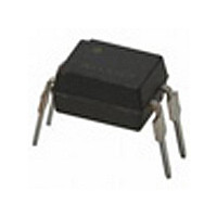
GP2S24AB Sharp Electronics, GP2S24AB Datasheet

GP2S24AB
Specifications of GP2S24AB
Related parts for GP2S24AB
GP2S24AB Summary of contents
Page 1
GP2S24J0000F Series ■ Description GP2S24J0000F Series is a compact-package, photo- transistor output, refl ective photointerrupter, with emitter and detector facing the same direction in a molding that provides non-contact sensing. The compact package series is a result of unique technology, ...
Page 2
Internal Connection Diagram ■ Outline Dimensions Top view 1.75 ±0.2 ∗4 +0.2 +0 −0.1 −0.1 4−(0.5) +0.2 +0.2 4−0.4 4−0.15 −0.1 −0.1 (4) θ ±15° θ ...
Page 3
Date code (Symbol) January February March April May June Rank mark There is no rank indicator. Country of origin Japan July August September October November December 3 GP2S24J0000F Series Sheet No.: D3-A01801EN ...
Page 4
Absolute Maximum Ratings Parameter Forward current Input Reverse voltage Power dissipation Collector-emitter voltage Emitter-collector voltage Output Collector current Collector power dissipation Total power dissipation Operating temperature Storage temperature ∗ 1 Soldering temperature ∗ 1 For 5s or less ■ ...
Page 5
... Model Line-up Model No. Rank GP2S24J0000F GP2S24BJ000F B GP2S24CJ000F C GP2S24ABJ00F GP2S24BCJ00F ∗ The ratio of each rank can not be guaranteed. Please contact a local SHARP sales representative to inquire about production status. Collector current I [ μ 4mA 2V 25˚ 120 120 120 5 GP2S24J0000F Series Sheet No.: D3-A01801EN ...
Page 6
Fig.1 Forward Current vs. Ambient Temperature − Ambient temperature T Fig.3 Forward Current vs. Forward Voltage T =75˚C a 50˚C 25˚C 100 0.5 1 1.5 Forward voltage ...
Page 7
Fig.7 Collector Dark Current vs. Ambient Temperature − =20V CE −7 10 −8 10 −9 10 − Ambient temperature T Fig.9 Test Circuit for Response Time V CC Reflector Input Plate ...
Page 8
Fig.13 Test Condition for Distance & Detecting Position Characteristics Al evaporated glass Correspond to Fig.10 Correspond to Fig.11 Test condition I = 4mA 1mm OMS card White Black d d 1mm − L=0 ...
Page 9
Design Considerations ● Design guide 1) Prevention of detection error To prevent photointerrupter from faulty operation caused by external light, do not set the detecting face to the external light. 2) Distance characteristic Please refer to Fig.10 (Relative collector ...
Page 10
Manufacturing Guidelines ● Soldering Method Flow Soldering: Soldering should be completed below 260˚C and within 5 s. Soldering area is 1mm or more away from the bottom of housing. Please take care not to let any external force exert ...
Page 11
Package specifi cation ● Sleeve package Package materials Sleeve : Polystyrene Stopper : Styrene-Butadiene Package method MAX. 50 pcs. of products shall be packaged in a sleeve. Both ends shall be closed by tabbed and tabless stoppers. MAX. 40 ...
Page 12
Important Notices · The circuit application examples in this publication are provided to explain representative applications of SHARP devices and are not intended to guarantee any circuit design or license any intellectual property rights. SHARP takes no responsibility for ...


