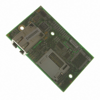
20-101-1139 Rabbit Semiconductor, 20-101-1139 Datasheet - Page 110

20-101-1139
Manufacturer Part Number
20-101-1139
Description
RCM4310 RABBITCORE
Manufacturer
Rabbit Semiconductor
Datasheet
1.20-101-1139.pdf
(124 pages)
Specifications of 20-101-1139
Module/board Type
MPU Core Module
Product
Microcontroller Modules
Data Bus Width
8 bit
Core Processor
Rabbit 4000
Clock Speed
58.98 MHz
Interface Type
Ethernet
Flash
1 MByte
Timers
10 x 8 bit
Operating Supply Voltage
3.3 V
Board Size
72 mm x 47 mm x 21 mm
For Use With/related Products
RCM4310
Lead Free Status / RoHS Status
Lead free / RoHS Compliant
Other names
316-1142
Available stocks
Company
Part Number
Manufacturer
Quantity
Price
B.4.3 Analog Features (RCM4300 only)
The Prototyping Board has typical support circuitry installed to complement the ADS7870
A/D converter on the RCM4300 model (the A/D converter is not available on the
RCM4210 model).
B.4.3.1 A/D Converter Inputs
Figure B-6 shows a pair of A/D converter input circuits. The resistors form an approx. 11:1
attenuator, and the capacitor filters noise pulses from the A/D converter input. The 470
inline jumpers allow other configurations (see Table B-6) and provide digital isolation when
you are not using an A/D converter (Parallel Port D is available). These jumpers optimize
using RabbitCore modules with or without A/D converters—if you are designing your own
circuit, the best performance for the A/D converter would be realized with 0 resistors.
The A/D converter chip can make either single-ended or differential measurements
depending on the value of the
A/D converter inputs are paired to make differential measurements. The default setup on
the Prototyping Board is to measure only positive voltages for the ranges listed in Table B-3.
RabbitCore RCM4300 User’s Manual
Min. Voltage
(V)
0.0
0.0
0.0
0.0
0.0
0.0
0.0
0.0
Table B-3. Positive A/D Converter Input Voltage Ranges
(with prescaler)
Max. Voltage
+22.528
+11.264
+5.632
+4.506
+2.816
+2.253
+1.408
+1.126
(V)
Figure B-6. A/D Converter Inputs
W
W
opmode
parameter in the software function call. Adjacent
Multiplier
Gain
×10
×16
×20
×1
×2
×4
×5
×8
W
A/D Converter
Actual Gain
14.4
1.8
3.6
4.5
7.2
9.0
18
1
Resolution
(mV)
1.375
1.100
0.688
0.550
2.75
2.20
5.5
11
110


