20-101-1139 Rabbit Semiconductor, 20-101-1139 Datasheet - Page 41
20-101-1139
Manufacturer Part Number
20-101-1139
Description
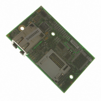
RCM4310 RABBITCORE
Manufacturer
Rabbit Semiconductor
Datasheet
1.20-101-1139.pdf
(124 pages)
Specifications of 20-101-1139
Module/board Type
MPU Core Module
Product
Microcontroller Modules
Data Bus Width
8 bit
Core Processor
Rabbit 4000
Clock Speed
58.98 MHz
Interface Type
Ethernet
Flash
1 MByte
Timers
10 x 8 bit
Operating Supply Voltage
3.3 V
Board Size
72 mm x 47 mm x 21 mm
For Use With/related Products
RCM4310
Lead Free Status / RoHS Status
Lead free / RoHS Compliant
Other names
316-1142
Available stocks
Company
Part Number
Manufacturer
Quantity
Price


4.4 A/D Converter (RCM4300 only)
The RCM4300 has an onboard ADS7870 A/D converter whose scaling and filtering are
done via the motherboard on which the RCM4300 module is mounted. The A/D converter
multiplexes converted signals from eight single-ended or four differential inputs to Serial
Port B on the Rabbit 4000.
The eight analog input pins, LN0–LN7, each have an input impedance of 6–7 M,
depending on whether they are used as single-ended or differential inputs. The input signal
can range from -2 V to +2 V (differential mode) or from 0 V to +2 V (single-ended mode).
Use a resistor divider such as the one shown in Figure 10 to measure voltages above 2 V
on the analog inputs.
Figure 10. Resistor Divider Network for Analog Inputs
The R1 resistors are typically 20 k to 100 k, with a lower resistance leading to more
accuracy, but at the expense of a higher current draw. The R0 resistors would then be
180 k to 900 k for a 10:1 attenuator. The capacitor filters noise pulses on the A/D
converter input.
The actual voltage range for a signal going to the A/D converter input is also affected by
the 1, 2, 4, 5, 8, 10, 16, and 20 V/V software-programmable gains available on each channel
of the ADS7870 A/D converter. Thus, you must scale the analog signal with an attenuator
circuit and a software-programmable gain so that the actual input presented to the A/D
converter is within the range limits of the ADS7870 A/D converter chip (-2 V to + 2 V or
0 V to + 2 V).
The A/D converter chip can only accept positive voltages. With the R1 resistors connected
to ground, your analog circuit is well-suited to perform positive A/D conversions. When
the R1 resistors are tied to ground for differential measurements, both differential inputs
must be referenced to analog ground, and both inputs must be positive with respect to
analog ground.
RabbitCore RCM4300 User’s Manual
41
Related parts for 20-101-1139
Image
Part Number
Description
Manufacturer
Datasheet
Request
R

Part Number:
Description:
COMPUTER SGL-BRD BL2500 29.4MHZ
Manufacturer:
Rabbit Semiconductor
Datasheet:

Part Number:
Description:
COMPUTER SGL-BRD BL2500 29.4MHZ
Manufacturer:
Rabbit Semiconductor
Datasheet:

Part Number:
Description:
DISPLAY GRAPHIC 12KEY PROG OP670
Manufacturer:
Rabbit Semiconductor
Datasheet:
Part Number:
Description:
DISPLAY GRAPHIC 12KEY ETH OP6700
Manufacturer:
Rabbit Semiconductor
Datasheet:

Part Number:
Description:
COMPUTER SINGLE-BOARD BL2030
Manufacturer:
Rabbit Semiconductor
Part Number:
Description:
COMPUTER SGL-BOARD ETH BL2010
Manufacturer:
Rabbit Semiconductor

Part Number:
Description:
MODULE OP6810 W/O ETH/MEM EXPANS
Manufacturer:
Rabbit Semiconductor
Datasheet:
Part Number:
Description:
COMPUTER SINGLE-BOARD BL2020
Manufacturer:
Rabbit Semiconductor
Part Number:
Description:
COMPUTER BL2010 W/FRICTION LOCK
Manufacturer:
Rabbit Semiconductor
Part Number:
Description:
COMPUTER BL2020 W/FRICTION LOCK
Manufacturer:
Rabbit Semiconductor
Part Number:
Description:
COMPUTER SGL-BRD BL2500 44.2MHZ
Manufacturer:
Rabbit Semiconductor
Datasheet:
Part Number:
Description:
COMPUTER SGL-BOARD FULL BL2000
Manufacturer:
Rabbit Semiconductor

Part Number:
Description:
COMPUTER SINGLE-BOARD BL2110
Manufacturer:
Rabbit Semiconductor

Part Number:
Description:
COMPUTER SGL-BRD 29.4MHZ BL2610
Manufacturer:
Rabbit Semiconductor
Datasheet:
Part Number:
Description:
INTERFACE OP6800 512K FLASH&SRAM
Manufacturer:
Rabbit Semiconductor
Datasheet: