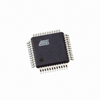
AT43USB326-AU Atmel, AT43USB326-AU Datasheet - Page 40

AT43USB326-AU
Manufacturer Part Number
AT43USB326-AU
Description
IC USB KEYBOARD CTRLR 48LQFP
Manufacturer
Atmel
Series
AVR®r
Datasheet
1.AT43USB326-AC.pdf
(102 pages)
Specifications of AT43USB326-AU
Applications
Keyboard Controller
Core Processor
AVR
Program Memory Type
Mask ROM (16 kB)
Controller Series
AT43USB
Ram Size
512 x 8
Interface
USB
Number Of I /o
32
Voltage - Supply
4.4 V ~ 5.25 V
Operating Temperature
-40°C ~ 85°C
Mounting Type
Surface Mount
Package / Case
48-LQFP
Lead Free Status / RoHS Status
Lead free / RoHS Compliant
Available stocks
Company
Part Number
Manufacturer
Quantity
Price
I/O Ports
40
AT43USB326
1. In the same operation, write a logical one to WDTOE and WDE. A logical one must be
2. Within the next four clock cycles, write a logical 0 to WDE. This disables the watchdog.
• Bits 2..0 – WDP2, WDP1, WDP0: Watch Dog Timer Prescaler 2, 1 and 0
The WDP2, WDP1 and WDP0 bits determine the Watchdog Timer prescaling when the
Watchdog Timer is enabled. The different prescaling values and their corresponding Time-out
Periods are shown in Table 11.
Table 11. Watchdog Timer Prescale Select
Note:
All AVR ports have true Read-Modify-Write functionality when used as general digital I/O
ports. This means that the direction of one port pin can be changed without unintentionally
changing the direction of any other pin with the SBI and CBI instructions. The same applies for
changing drive value if configured as output or enabling/disabling of pull-up resistors if config-
ured as input.
The keyboard matrix strobe output pins, PA[0:7], PB[0:7] and PE[0:1] have controlled slope
drivers. With a load of 100 pF, the output fall time ranges between 75 ns and 300 ns. The key-
board matrix strobe input pins, PC[0:7] have built-in pull-up resistors, 20 KΩ nominal value, to
the internal 3.3V power supply.
PE[4:7] have 5V tolerant outputs and each has a built-in series resistor of 330Ω nominal value.
These output pins are designed for driving an LED connected to the 5V supply.
The dedicated functions are summarized in Table 12.
Table 12. GPIO Function Assignments
Function
Scan out[0:7]
Scan out[8:15]
Scan out[16,17]
Scan in[0:7]
LED drivers
WDP2
written to WDE even though it is set to one before the disable operation starts.
0
0
0
0
1
1
1
1
The WDR (Watchdog Reset) instruction should always be executed before the Watchdog Timer
is enabled. This ensures that the reset period will be in accordance with the Watchdog Timer
prescale settings. If the Watchdog Timer is enabled without reset, the watchdog timer may not
start to count from zero. To avoid unintentional MCU reset, the Watchdog Timer should be dis-
abled or reset before changing the Watchdog Timer Prescale Select.
WDP1
0
0
1
1
0
0
1
1
WDP0
0
1
0
1
0
1
0
1
Number of WDT Oscillator cycles
8K cycles
16K cycles
32K cycles
64K cycles
128K cycles
256K cycles
512K cycles
1,024K cycles
GPIO
PA[0:7]
PB[0:7]
PE[0,1]
PC[0:7]
PE[4:7]
Time-out
8.2 ms
16.4 ms
33.8 ms
65.6 ms
0.131 s
0.262 s
0.524 s
1.048 s
3313D–USB–04/06


