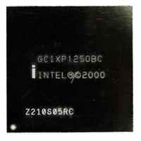
GCIXP1250BC Intel, GCIXP1250BC Datasheet - Page 18

GCIXP1250BC
Manufacturer Part Number
GCIXP1250BC
Description
IC MPU NETWORK 232MHZ 520-BGA
Manufacturer
Intel
Specifications of GCIXP1250BC
Rohs Status
RoHS non-compliant
Processor Type
Network
Features
32-bit StrongARM RISC Core
Speed
232MHz
Voltage
3.3V
Mounting Type
Surface Mount
Package / Case
520-BGA
Pin Count
520
Mounting
Surface Mount
Operating Temperature (max)
85C
Operating Temperature (min)
-40C
Operating Temperature Classification
Industrial
Lead Free Status / Rohs Status
Not Compliant
Other names
837414
Available stocks
Company
Part Number
Manufacturer
Quantity
Price
Company:
Part Number:
GCIXP1250BC
Manufacturer:
INTEL
Quantity:
77
Intel
Errata
19.
Problem:
Implication:
Workaround:
Status:
20.
Problem:
Implication:
Workaround:
18
®
IXP1250 Network Processor
Find Bit
Find Bit works on the software model but not in the actual hardware. The operation returns zero
when a non-zero result is expected.
; Demonstration of find_bset_with_mask erratum
;
; The data register is loaded with all 1’s
; Then we do a find_bset_with_mask with a mask of 0x10,
; which should find bit 4 as the first bit set.
; On hardware, the result comes back as zero indicating no bit set.
immed[data, -1]
find_bset_with_mask[0x10, data], clr_results
nop
nop
nop
nop
nop
nop
load_bset_result1[result] ; should result in 0x104
nop
nop
nop
lab#: br [lab#]
Wrong Find Bit.
Do not use the FIND_BSET_WITH_MASK instruction with an immediate mask operand.
Fixed
SDRAM_CRC Residue Register Corrupted Data
An sdram_crc[write, ..], initiate command, under certain conditions, may result in corrupted data
in the Residue register.
During an alignment operation of >=4 bytes, an additional cycle is required for the operation to
complete when compared to an alignment of < 4 bytes. If an sdram_crc[write, ..], initiate
command is issued immediately after an alignment operation of >= 4 bytes, the additional cycle
blocks the CRC Residue register write resulting in a corrupted residue value.
Two software workarounds exist for software designs doing both sdram[tfifo_wr, ]byte-align>=4
and CRC calculations sequences. The workarounds insert one cycle between the last
sdram[tfifo_wr, ]byte-align>=4 and the sdram_crc[write],initiate that immediately follows.
Workaround 1: This workaround is recommended due to the ease of implementation. An extra
cycle between all read and write operations is effected by programming the Read-Write
Turnaround time(tRWT) value in the SDRAM CSR register to at least 0x2. The tRWT value of 0x2
places two unused cycles on the SDRAM pins between every read and write, as opposed to the
required one.
The simulator will detect if this problem could occur in the simulating program and will print a
warning if Workaround 1 is not used.
Workaround 2: The workaround is to always insert a regular SDRAM read without any byte
alignment immediately before the CRC initiation. An example of this workaround is to chain an
sdram[read] to every sdram[tfifo_wr],byte-align>=4 and to place these requests in any queue
Specification Update


