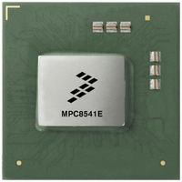
MPC8541EVTAQF Freescale Semiconductor, MPC8541EVTAQF Datasheet - Page 70

MPC8541EVTAQF
Manufacturer Part Number
MPC8541EVTAQF
Description
IC MPU POWERQUICC III 783-FCPBGA
Manufacturer
Freescale Semiconductor
Datasheet
1.MPC8541EVTALF.pdf
(88 pages)
Specifications of MPC8541EVTAQF
Processor Type
MPC85xx PowerQUICC III 32-Bit
Speed
1.0GHz
Voltage
1.3V
Mounting Type
Surface Mount
Package / Case
783-FCPBGA
Processor Series
MPC85xx
Core
e500
Data Bus Width
32 bit
Development Tools By Supplier
RDK-IDM-SBC
Maximum Clock Frequency
1000 MHz
Maximum Operating Temperature
+ 105 C
Mounting Style
SMD/SMT
I/o Voltage
2.5 V, 3.3 V
Minimum Operating Temperature
0 C
For Use With
MPC8548CDS - DEV TOOLS CDS FOR 8548CWH-PPC-8540N-VE - KIT EVAL SYSTEM MPC8540
Lead Free Status / RoHS Status
Lead free / RoHS Compliant
Features
-
Lead Free Status / Rohs Status
Lead free / RoHS Compliant
Available stocks
Company
Part Number
Manufacturer
Quantity
Price
Company:
Part Number:
MPC8541EVTAQF
Manufacturer:
Freescale Semiconductor
Quantity:
10 000
Thermal
16.2.2
For the packaging technology, shown in
are as follows:
Figure 44
printed-circuit board.
The heat sink removes most of the heat from the device. Heat generated on the active side of the chip is
conducted through the silicon and through the lid, then through the heat sink attach material (or thermal
interface material), and finally to the heat sink. The junction-to-case thermal resistance is low enough that
the heat sink attach material and heat sink thermal resistance are the dominant terms.
16.2.3
A thermal interface material is required at the package-to-heat sink interface to minimize the thermal
contact resistance. For those applications where the heat sink is attached by spring clip mechanism,
Figure 45
graphite/oil, floroether oil), a bare joint, and a joint with thermal grease as a function of contact pressure.
As shown, the performance of these thermal interface materials improves with increasing contact pressure.
The use of thermal grease significantly reduces the interface thermal resistance. The bare joint results in a
thermal resistance approximately six times greater than the thermal grease joint.
Heat sinks are attached to the package by means of a spring clip to holes in the printed-circuit board (see
Figure
interface pressure.
When removing the heat sink for re-work, it is preferable to slide the heat sink off slowly until the thermal
interface material loses its grip. If the support fixture around the package prevents sliding off the heat sink,
70
•
•
41). Therefore, the synthetic grease offers the best thermal performance, especially at the low
The die junction-to-case thermal resistance
The die junction-to-board thermal resistance
MPC8541E PowerQUICC™ III Integrated Communications Processor Hardware Specification, Rev. 4.2
depicts the primary heat transfer path for a package with an attached heat sink mounted to a
shows the thermal performance of three thin-sheet thermal-interface materials (silicone,
Internal Package Conduction Resistance
Thermal Interface Materials
(Note the internal versus external package resistance)
External Resistance
External Resistance
Internal Resistance
Figure 44. Package with Heat Sink Mounted to a Printed-Circuit Board
Printed-Circuit Board
Heat Sink
Table
49, the intrinsic internal conduction thermal resistance paths
Radiation
Radiation
Convection
Convection
Thermal Interface Material
Die/Package
Die Junction
Package/Leads
Freescale Semiconductor


