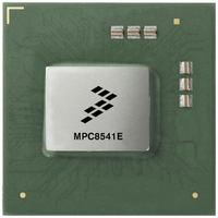
MPC8541EVTAQF Freescale Semiconductor, MPC8541EVTAQF Datasheet - Page 9

MPC8541EVTAQF
Manufacturer Part Number
MPC8541EVTAQF
Description
IC MPU POWERQUICC III 783-FCPBGA
Manufacturer
Freescale Semiconductor
Datasheet
1.MPC8541EVTALF.pdf
(88 pages)
Specifications of MPC8541EVTAQF
Processor Type
MPC85xx PowerQUICC III 32-Bit
Speed
1.0GHz
Voltage
1.3V
Mounting Type
Surface Mount
Package / Case
783-FCPBGA
Processor Series
MPC85xx
Core
e500
Data Bus Width
32 bit
Development Tools By Supplier
RDK-IDM-SBC
Maximum Clock Frequency
1000 MHz
Maximum Operating Temperature
+ 105 C
Mounting Style
SMD/SMT
I/o Voltage
2.5 V, 3.3 V
Minimum Operating Temperature
0 C
For Use With
MPC8548CDS - DEV TOOLS CDS FOR 8548CWH-PPC-8540N-VE - KIT EVAL SYSTEM MPC8540
Lead Free Status / RoHS Status
Lead free / RoHS Compliant
Features
-
Lead Free Status / Rohs Status
Lead free / RoHS Compliant
Available stocks
Company
Part Number
Manufacturer
Quantity
Price
Company:
Part Number:
MPC8541EVTAQF
Manufacturer:
Freescale Semiconductor
Quantity:
10 000
Items on the same line have no ordering requirement with respect to one another. Items on separate lines
must be ordered sequentially such that voltage rails on a previous step must reach 90 percent of their value
before the voltage rails on the current step reach ten percent of theirs.
2.1.3
Table 2
Table 2
conditions is not guaranteed.
Freescale Semiconductor
Core supply voltage
PLL supply voltage
DDR DRAM I/O voltage
Three-speed Ethernet I/O voltage
PCI, local bus, DUART, system control and power management,
I
Input voltage
Die-junction Temperature
2
C, and JTAG I/O voltage
MPC8541E PowerQUICC™ III Integrated Communications Processor Hardware Specification, Rev. 4.2
provides the recommended operating conditions for the MPC8541E. Note that the values in
are the recommended and tested operating conditions. Proper device operation outside of these
Recommended Operating Conditions
If the items on line 2 must precede items on line 1, please ensure that the
delay does not exceed 500 ms and the power sequence is not done greater
than once per day in production environment.
From a system standpoint, if the I/O power supplies ramp prior to the V
core supply, the I/Os on the MPC8541E may drive a logic one or zero during
power-up.
Characteristic
DDR DRAM signals
DDR DRAM reference
Three-speed Ethernet signals
PCI, local bus, DUART,
SYSCLK, system control and
power management, I
JTAG signals
Table 2. Recommended Operating Conditions
2
C, and
NOTE
NOTE
Symbol
MV
GV
OV
AV
LV
MV
OV
LV
V
T
DD
REF
DD
DD
DD
DD
IN
j
IN
IN
1.3 V ± 50 mV (for 1 GHz only)
1.3 V± 50 mV (for 1 GHz only)
Recommended Value
2.5 V ± 125 mV
3.3 V ± 165 mV
2.5 V ± 125 mV
3.3 V ± 165 mV
1.2 V ± 60 mV
1.2 V ± 60 mV
GND to GV
GND to GV
GND to OV
GND to LV
0 to 105
DD
DD
DD
DD
Electrical Characteristics
DD
Unit
°C
V
V
V
V
V
V
V
V
V
9


