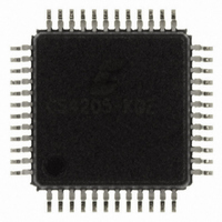
CS4205-KQZ Cirrus Logic Inc, CS4205-KQZ Datasheet - Page 68

CS4205-KQZ
Manufacturer Part Number
CS4205-KQZ
Description
IC CODEC AC97 I2S 48-LQFP
Manufacturer
Cirrus Logic Inc
Type
Audio Codec '97r
Datasheet
1.CS4205-KQZ.pdf
(81 pages)
Specifications of CS4205-KQZ
Package / Case
48-LQFP
Data Interface
Serial
Resolution (bits)
18, 20 b
Number Of Adcs / Dacs
1 / 2
Sigma Delta
Yes
Dynamic Range, Adcs / Dacs (db) Typ
90 / 90
Voltage - Supply, Analog
4.75 V ~ 5.25 V
Voltage - Supply, Digital
4.75 V ~ 5.25 V
Operating Temperature
0°C ~ 70°C
Mounting Type
Surface Mount
Number Of Adc Inputs
8
Number Of Dac Outputs
3
Conversion Rate
48 KSPs
Interface Type
Serial (5-Wire)
Resolution
18 bit, 20 bit
Maximum Operating Temperature
+ 70 C
Mounting Style
SMD/SMT
Minimum Operating Temperature
0 C
Number Of Channels
1 ADC, 1 DAC
Lead Free Status / RoHS Status
Lead free / RoHS Compliant
Other names
598-1182
Available stocks
Company
Part Number
Manufacturer
Quantity
Price
Company:
Part Number:
CS4205-KQZ
Manufacturer:
Vishay
Quantity:
718
Company:
Part Number:
CS4205-KQZR
Manufacturer:
Cirrus Logic Inc
Quantity:
10 000
13. GROUNDING AND LAYOUT
Figure 33 on page 69 shows the conceptual layout
for the CS4205 in XTAL or OSC clocking modes.
The decoupling capacitors should be located phys-
ically as close to the pins as possible. Also, note the
connection of the REFFLT decoupling capacitors
to the ground return trace connected directly to the
ground return pin, AVss1.
It is strongly recommended that separate analog
and digital ground planes be used. Separate ground
planes keep digital noise and return currents from
modulating the CS4205 ground potential and de-
grading performance. The digital ground pins
should be connected to the digital ground plane and
kept separate from the analog ground connections
of the CS4205 and any other external analog cir-
cuitry. All analog components and traces should be
located over the analog ground plane and all digital
components and traces should be located over the
digital ground plane.
The common connection point between the two
ground planes (required to maintain a common
ground voltage potential) should be located under
the CS4205. The AC-link digital interface connec-
68
tion traces should be routed such that the digital
ground plane lies underneath these signals (on the
internal ground layer). This applies along the entire
length of these traces from the AC ’97 controller to
the CS4205.
Refer to the Application Note AN18: Layout and
Design Rules for Data Converters and Other
Mixed Signal Devices [2] for more information on
layout and design rules.
CS4205
DS489PP4


