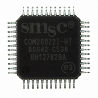
COM20022I-HT SMSC, COM20022I-HT Datasheet - Page 8

COM20022I-HT
Manufacturer Part Number
COM20022I-HT
Description
IC CTRLR ARCNET 2KX8 RAM 48-TQFP
Manufacturer
SMSC
Series
ARCNETr
Datasheet
1.COM20022I3V-HT.pdf
(82 pages)
Specifications of COM20022I-HT
Controller Type
ARCNET Controller
Interface
Differential
Voltage - Supply
4.5 V ~ 5.5 V
Current - Supply
65mA
Operating Temperature
-40°C ~ 85°C
Mounting Type
Surface Mount
Package / Case
48-TQFP, 48-VQFP
Lead Free Status / RoHS Status
Lead free / RoHS Compliant
Other names
638-1003
Available stocks
Company
Part Number
Manufacturer
Quantity
Price
Company:
Part Number:
COM20022I-HT
Manufacturer:
Standard
Quantity:
5 410
Company:
Part Number:
COM20022I-HT
Manufacturer:
SMSC
Quantity:
455
Company:
Part Number:
COM20022I-HT
Manufacturer:
Microchip Technology
Quantity:
10 000
Chapter 3
Revision 09-27-07
10,12, 13
PIN NO
47, 48,
44,45,
14-17
1,2,4,
7,9,
3,5,
46
37
39
31
34
36
42
26
33
35
38
40
Address 0-2
Data 0-7
Data 8-15
nWrite/
Direction
nRead/
nData Strobe
nReset In
nInterrupt
nChip Select
nI/O
16 Bit
Indicator
Read/Write
Bus Timing
Select
DMA
Request
DMA Ack
Terminal
Count
Refresh
Execution
NAME
Description of Pin Functions
A0/nMUX
A1
A2/ALE
AD0-AD2,
D3-D7
D8-D15
nWR/DIR
nRD/nDS
nRESET
nINTR
nCS
nIOCS16
BUSTMG
DREQ
nDACK
TC
nREFEX
SYMBOL
MICROCONTROLLER INTERFACE
DATASHEET
IN
IN
IN
I/O
I/O
IN
IN
IN
OUT
IN
OUT
IN
OUT
IN
IN
IN
I/O
Page 8
On a non-multiplexed mode, A0-A2 are address input bits.
(A0 is the LSB) On a multiplexed address/data bus, nMUX
tied Low, A1 is left open, and ALE is tied to the Address
Latch Enable signal. A1 is connected to an internal pull-up
resistor.
On a non-multiplexed bus, these signals are used as the
lower byte data bus lines. On a multiplexed address/data
bus, AD0-AD2 act as the address lines (latched by ALE)
and as the low data lines. D3-D7 are always used for data
only. These signals are connected to internal pull-up
resistors.
D8-D15 are always used as the higher byte data bus lines
only for 16bit internal RAM access. When the 16bit access
is disabled, these signals are always Hi-Z. Enabling or
disabling the 16bit access is programmable. A data
swapper is built in. These signals are connected to internal
pull-up resistors.
nWR is for 80xx CPU, nWR is Write signal input. Active
Low.
DIR is for 68xx CPU, DIR is Bus Direction signal input.
(Low: Write, High: Read.)
nRD is for 80xx CPU, nRD is Read signal input. Active Low.
nDS is for 68xx CPU, nDS is Data Strobe signal input.
Active Low.
Hardware reset signal. Active Low.
Interrupt signal output. Active Low.
Chip Select input. Active Low.
This signal is an active Low signal which indicates
accessing 16bit data only by CPU. This signal becomes
active when CPU accesses to data register only if W16 bit
is 1. This signal is same as on ISA Bus signal, but it’s not
OPEN-DRAIN. An external OPEN-DRAIN Buffer is needed
when this signal connects to the ISA Bus.
Read and Write Bus Access Timing mode selecting signal.
Status of this signal effects CPU and DMA Timing.
L: High speed timing mode (only for non-multiplexed bus)
H: Normal timing mode
This signal is connected to internal pull-up registers.
DMA Request signal. Active polarity is programmable.
Default is active high.
DMA Acknowledge signal. Active Low. When BUSTMG is
High, this signal is connected to internal pull-up registers
Terminal Count signal. Active polarity is programmable.
Default is active high. When BUSTMG is High, this signal is
connected to the internal pull-up resistor.
Refresh execution signal. Falling edge detection. This
signal is connected to the internal pull-up resistor.
10 Mbps ARCNET (ANSI 878.1) Controller with 2Kx8 On-Chip RAM
DESCRIPTION
SMSC COM20022I
Datasheet


