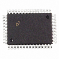
DP83902AVLJ National Semiconductor, DP83902AVLJ Datasheet - Page 13

DP83902AVLJ
Manufacturer Part Number
DP83902AVLJ
Description
IC CTRLR SER NETWORK IN 100PQFP
Manufacturer
National Semiconductor
Datasheet
1.DP83902AVJGNOPB.pdf
(70 pages)
Specifications of DP83902AVLJ
Controller Type
Serial Network Interface Controller
Interface
Serial
Voltage - Supply
4.75 V ~ 5.25 V
Current - Supply
140mA
Operating Temperature
0°C ~ 70°C
Mounting Type
Surface Mount
Package / Case
100-MQFP, 100-PQFP
Lead Free Status / RoHS Status
Contains lead / RoHS non-compliant
Other names
*DP83902AVLJ
Available stocks
Company
Part Number
Manufacturer
Quantity
Price
Company:
Part Number:
DP83902AVLJ
Manufacturer:
NS
Quantity:
2 500
Company:
Part Number:
DP83902AVLJ
Manufacturer:
RAYCHEM
Quantity:
2 500
Company:
Part Number:
DP83902AVLJ
Manufacturer:
Texas Instruments
Quantity:
10 000
Part Number:
DP83902AVLJ
Manufacturer:
NS/国半
Quantity:
20 000
5 0 Transmit Receive Packet
Encapsulation Decapsulation
(Continued)
SOURCE ADDRESS
The source address is the physical address of the node that
sent the packet Source addresses cannot be multicast or
broadcast addresses This field is simply passed to buffer
memory
LENGTH TYPE FIELD
The 2-byte length field indicates the number of bytes that
are contained in the data field of the packet This field is not
interpreted by the ST-NIC
DATA FIELD
The data field consists of anywhere from 46 to 1500 bytes
Messages longer than 1500 bytes need to be broken into
multiple packets Messages shorter than 46 bytes will re-
quire appending a pad to bring the data field to the minimum
length of 46 bytes If the data field is padded the number of
valid data bytes is indicated in the length field The ST-NIC
does not strip or append pad bytes for short packets
or check for oversize packets
FCS FIELD
The Frame Check Sequence (FCS) is a 32-bit CRC field
calculated and appended to a packet during transmission to
allow detection of errors when a packet is received During
reception error free packets result in a specific pattern in
the CRC generator Packets with improper CRC will be re-
jected The AUTODIN II (X
X
polynomial is used for the CRC calculations
12
a
X
11
a
X
10
a
X
8
a
32
X
7
a
a
X
26
X
5
a
a
X
X
23
4
a
a
X
X
2
22
a
a
X
1
X
16
Dual Bus System
a
a
1)
13
6 0 Direct Memory Access
Control (DMA)
The DMA capabilities of the ST-NIC greatly simplify the use
of the DP83902A in typical configurations The local DMA
channel transfers data between the FIFO and memory On
transmission the packet is DMAed from memory to the
FIFO in bursts Should a collision occur (up to 15 times) the
packet is retransmitted with no processor intervention On
reception packets are DMAed from the FIFO to the receive
buffer ring (as explained below)
dA remote DMA channel is also provided on the ST-NIC to
accomplish transfers between a buffer memory and system
memory The two DMA channels can alternatively be com-
bined to form a single 32-bit address with 8- or 16-bit data
DUAL DMA CONFIGURATION
An example configuration using both the local and remote
DMA channels is shown below Network activity is isolated
on a local bus where the ST-NIC’s local DMA channel per-
forms burst transfers between the buffer memory and the
ST-NIC’s FIFO The Remote DMA transfers data between
the buffer memory and the host memory via a bidirectional
I O port The Remote DMA provides local addressing capa-
bility and is used as a slave DMA by the host Host side
addressing must be provided by a host DMA or the CPU
The ST-NIC allows Local and Remote DMA operations to
be interleaved
SINGLE CHANNEL DMA OPERATION
If desirable the two DMA channels can be combined to
provide a 32-bit DMA address The upper 16 bits of the
32-bit address are static and are used to point to a 64 kbyte
(or 32k word) page of memory where packets are to be
received and transmitted
TL F 11157– 8


