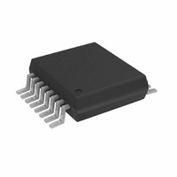
AD5934YRSZ Analog Devices Inc, AD5934YRSZ Datasheet - Page 18

AD5934YRSZ
Manufacturer Part Number
AD5934YRSZ
Description
IC NTWK ANALYZER 12B 1MSP 16SSOP
Manufacturer
Analog Devices Inc
Datasheet
1.AD5934YRSZ.pdf
(40 pages)
Specifications of AD5934YRSZ
Resolution (bits)
12 b
Master Fclk
16.776MHz
Voltage - Supply
2.7 V ~ 5.5 V
Operating Temperature
-40°C ~ 125°C
Mounting Type
Surface Mount
Package / Case
16-SSOP
Supply Voltage Range
2.7V To 5.5V
Operating Temperature Range
-40°C To +125°C
Digital Ic Case Style
SSOP
No. Of Pins
16
Frequency Max
0.1MHz
Termination Type
SMD
Filter Terminals
SMD
Rohs Compliant
Yes
Communication Function
Network Analyzer
Lead Free Status / RoHS Status
Lead free / RoHS Compliant
For Use With
EVAL-AD5934EBZ - BOARD EVALUATION FOR AD5934
Tuning Word Width (bits)
-
Lead Free Status / RoHS Status
Lead free / RoHS Compliant, Lead free / RoHS Compliant
Available stocks
Company
Part Number
Manufacturer
Quantity
Price
Company:
Part Number:
AD5934YRSZ
Manufacturer:
Analog Devices Inc
Quantity:
135
Company:
Part Number:
AD5934YRSZ
Manufacturer:
Maxim
Quantity:
289
Part Number:
AD5934YRSZ
Manufacturer:
ADI/亚德诺
Quantity:
20 000
Company:
Part Number:
AD5934YRSZ-REEL7
Manufacturer:
IR
Quantity:
114
AD5934
Impedance Range 3 (10 kΩ to 100 kΩ)
The following conditions were used to conduct the tests shown
in Figure 24:
Output excitation voltage = 2 V p-p
Calibration impedance value, Z
PGA gain = ×1
Supply voltage = 3.3 V
Current-to-voltage amplifier gain resistor = 10 kΩ
Impedance Range 4 (100 kΩ to 1 MΩ)
The following conditions were used to conduct the tests shown
in Figure 25:
Output excitation voltage = 2 V p-p
Calibration impedance value, Z
PGA gain = ×1
Supply voltage = 3.3 V
Current-to-voltage amplifier gain resistor = 100 kΩ
Figure 24. Impedance Range 3 Typical % Impedance Error over Frequency
Figure 25. Impedance Range 4 Typical % Impedance Error over Frequency
–0.1
–0.2
–0.3
–0.5
–1.0
–1.5
–2.0
–2.5
–3.0
–3.5
0.3
0.2
0.1
1.0
0.5
0
0
R
CALIBRATION IMPEDANCE = 100kΩ
T
R
CALIBRATION IMPEDANCE = 10kΩ
T
A
FB
A
FB
= 25°C
= 25°C
= 100kΩ
= 10kΩ
10
10
FREQUENCY (kHz)
FREQUENCY (kHz)
35
35
CALIBRATION
CALIBRATION
60
60
= 10 kΩ
= 100 kΩ
500kΩ
1MΩ
100
100
50kΩ
100kΩ
Rev. A | Page 18 of 40
Impedance Range 5 (1 MΩ to 2 MΩ)
The following conditions were used to conduct the tests shown
in Figure 26:
Output excitation voltage = 2 V p-p
Calibration impedance value, Z
PGA gain = ×1
Supply voltage = 3.3 V
Current-to-voltage amplifier gain resistor = 100 kΩ
Impedance Range 6 (9 MΩ to 10 MΩ)
The following conditions were used to conduct the tests shown
in Figure 27:
Output excitation voltage = 2 V p-p
Calibration impedance value, Z
PGA gain = ×1
Supply voltage = 3.3 V
Current-to-voltage amplifier gain resistor = 9 MΩ
Figure 26. Impedance Range 5 Typical % Impedance Error over Frequency
Figure 27. Impedance Range 6 Typical % Impedance Error over Frequency
–10
–1
–3
–5
–7
–9
–2
–4
–6
–8
3
1
4
2
0
R
CALIBRATION IMPEDANCE = 10MΩ
T
R
CALIBRATION IMPEDANCE = 1MΩ
T
A
A
FB
FB
1.5MΩ
2MΩ
= 25°C
= 25°C
9.5MΩ
10MΩ
= 1MΩ
= 10MΩ
10
10
FREQUENCY (kHz)
FREQUENCY (kHz)
35
35
CALIBRATION
CALIBRATION
60
60
= 100 kΩ
= 9 MΩ
100
100


