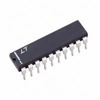
LTC1061CN Linear Technology, LTC1061CN Datasheet - Page 7

LTC1061CN
Manufacturer Part Number
LTC1061CN
Description
IC FILTER BUILDNG BLK TRPL 20DIP
Manufacturer
Linear Technology
Datasheet
1.LTC1061CNPBF.pdf
(16 pages)
Specifications of LTC1061CN
Filter Type
Universal Switched Capacitor
Frequency - Cutoff Or Center
35kHz
Number Of Filters
3
Max-order
6th
Voltage - Supply
4.74 V ~ 16 V, ±2.37 V ~ 8 V
Mounting Type
Through Hole
Package / Case
20-DIP (0.300", 7.62mm)
Lead Free Status / RoHS Status
Contains lead / RoHS non-compliant
Available stocks
Company
Part Number
Manufacturer
Quantity
Price
Company:
Part Number:
LTC1061CN
Manufacturer:
LT
Quantity:
5 510
Company:
Part Number:
LTC1061CN
Manufacturer:
TI
Quantity:
5 510
Company:
Part Number:
LTC1061CN#PBF
Manufacturer:
LT
Quantity:
872
W
V
Description and Applications
1. Primary Modes: There are two basic modes of opera-
tion, Mode 1 and Mode 3. In Mode 1, the ratio of the
external clock frequency to the center frequency of each
2nd order section is internally fixed at 50:1 or 100:1. In
Mode 3, this ratio can be adjusted above or below 50:1 or
100:1. The side C of the LTC1061 can be connected only
in Mode 3. Figure 3 illustrates Mode 1 providing 2nd order
notch, lowpass, and bandpass outputs (for definition of
filter functions, refer to the LTC1060 data sheet). Mode 1
can be used to make high order Butterworth lowpass
filters; it can also be used to make low Q notches and for
cascading 2nd order bandpass functions tuned at the
same center frequency and with unity-gain. Mode 3,
V
IN
IN
ODES OF OPERATIO
R1
R1
Figure 3. Mode 1: 2nd Order Filter Providing Notch,
Bandpass, Lowpass
Figure 4. Mode 3: 2nd Order Filter Providing Highpass,
Bandpass, Lowpass
NOTE: ADD C
AGND
AGND
+
–
–
+
C
R2
R3
R4
R3
R2
FOR Q > 5 AND f
f
H
Q =
O
OLP
=
100(50)
R3
R2
f
H
O
= –
f
OHP
CLK
=
100(50)
R2
R1
f
= –
CLK
1/3 LTC1061
N
; f
1/3 LTC1061
HP
; H
+
CLK
n
R2
R1
+
OBP
C
= f
Σ
√
C
; H
> 1MHz, SUCH AS C
O
Σ
R2
R4
–
= –
OBP
S
–
S
; Q =
R3
R1
= –
∫
; H
∫
U
R3
R1
R3
R2
ON1
; H
√
= –
R2
R4
OLP
R2
R1
C
BP
= –
BP
≅
∫
∫
R4
R1
R4 × 1.2MHz
1061 F03
1061 F04
0.16
LP
LP
Figure 4, is the classical state variable configuration pro-
viding highpass, bandpass and lowpass 2nd order filter
functions.
Since the input amplifier is within the resonant loop, its
phase shift affects the high frequency operation of the
filter and therefore, Mode 3 is slower than Mode 1. Mode
3 can be used to make high order all-pole bandpass,
lowpass, highpass and notch filters. Mode 3 as well as
Mode 1 is a straightforward mode to use and the filter’s
dynamics can easily be optimized. Figure 5 illustrates a 6th
order lowpass Butterworth filter operating with up to
40kHz cutoff frequency and with up to 200kHz input
frequency. Sides A, B are connected in Mode 1 while side
C is connected in Mode 3. The lower Q section was placed
in side C, Mode 3, to eliminate any early Q enhancement.
This could happen when the clock approaches 2MHz. The
measured frequency response is shown in Figure 6. The
attenuation floor is limited by the crosstalk between the
three different sections operating with a clock frequency
above 1MHz. The measured wideband noise was
150µV
Figure 5 works up to 2.5MHz clock frequency thus yielding
a 50kHz cutoff.
T
HARMONIC DISTORTION WITH f
Figure 5. 6th Order Butterworth Lowpass Filter with
Cutoff Frequency up to 45kHz
2
< 2.5MHz
L CLOCK
10kHz, 1V
20kHz, 1V
30kHz, 1V
40kHz, 1V
RMS
V
V
f
IN
IN
+
. For limited temperature range the filter of
RMS
RMS
RMS
RMS
R13
R33
R23
2ND HARMONIC
10
1
2
3
4
5
6
7
8
9
–74dB
–62dB
–62dB
–62dB
CLK
LTC1061
= 2MHz
20
19
18
17
16
15
14
13
12
11
R11 = 20k
R31 = 11k
R12 = 20k
R32 = 14k
R13 = 10k
RESISTOR VALUES
STANDARD 1%
V
R32
R22
–
LTC1061
R21 = 20k
R41 = 20k
R22 = 20k
R23 = 10k
R33 = 17.8k
V
OUT
R12
R41
R31
R21
R11
LTC1061 F05
1061fe
7


