MCP23018-E/MJ Microchip Technology, MCP23018-E/MJ Datasheet - Page 24
MCP23018-E/MJ
Manufacturer Part Number
MCP23018-E/MJ
Description
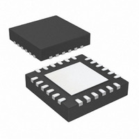
IC I/O EXPANDER I2C 16B 24QFN
Manufacturer
Microchip Technology
Datasheet
1.MCP23018-ESO.pdf
(56 pages)
Specifications of MCP23018-E/MJ
Package / Case
24-QFN
Interface
I²C
Number Of I /o
16
Interrupt Output
Yes
Frequency - Clock
3.4MHz
Voltage - Supply
1.8 V ~ 5.5 V
Operating Temperature
-40°C ~ 125°C
Mounting Type
Surface Mount
Logic Family
MCP23018
Propagation Delay Time
50 ns
Operating Supply Voltage
1.8 V to 5.5 V
Power Dissipation
700 mW
Operating Temperature Range
- 40 C to + 125 C
Input Voltage
1.8 V to 5.5 V
Logic Type
I/O Expander
Maximum Clock Frequency
10 MHz
Maximum Operating Frequency
3.4 MHz
Mounting Style
SMD/SMT
Output Current
25 mA
Output Voltage
1.8 V to 4.5 V
Lead Free Status / RoHS Status
Lead free / RoHS Compliant
Lead Free Status / RoHS Status
Lead free / RoHS Compliant, Lead free / RoHS Compliant
Available stocks
Company
Part Number
Manufacturer
Quantity
Price
Company:

Part Number:
MCP23018-E/MJ
Manufacturer:
Microchip
Quantity:
1 195
Part Number:
MCP23018-E/MJ
Manufacturer:
MICROCHIP/微芯
Quantity:
20 000


MCP23018/MCP23S18
REGISTER 1-8:
DS22103A-page 24
bit 7
Legend:
R = Readable bit
-n = Value at POR
bit 7
bit 6
bit 5
bit 4
bit 3
bit 2
bit 1
bit 0
R/W-0
BANK
BANK: Controls how the registers are addressed (see
1 = The registers associated with each port are separated into different banks
0 = The registers are in the same bank (addresses are sequential)
MIRROR: INT pins mirror bit
1 = The INT pins are internally connected in a wired OR configuration
0 = The INT pins are not connected. INTA is associated with Port A and INTB is associated with Port B
SEQOP: Sequential Operation mode bit.
1 = Sequential operation disabled, address pointer does not increment.
0 = Sequential operation enabled, address pointer increments.
Unimplemented: Reads as 0
Unimplemented: Reads as 0
ODR: Configures the INT pin as an open-drain output.
1 = Open-drain output (overrides the INTPOL bit).
0 = Active driver output (INTPOL bit sets the polarity).
INTPOL: Sets the polarity of the INT output pin.
1 = Active-high.
0 = Active-low.
INTCC: Interrupt Clearing Control
1 = Reading INTCAP register clears the interrupt
0 = Reading GPIO register clears the interrupt
MIRROR
R/W-0
IOCON – I/O EXPANDER CONFIGURATION REGISTER
W = Writable bit
‘1’ = Bit is set
SEQOP
R/W-0
U-0
-
U = Unimplemented bit, read as ‘0’
‘0’ = Bit is cleared
U-0
-
Figure 1-4
R/W-0
ODR
and
Figure
© 2008 Microchip Technology Inc.
x = Bit is unknown
INTPOL
R/W-0
1-5)
INTCC
R/W-0
bit 0
Related parts for MCP23018-E/MJ
Image
Part Number
Description
Manufacturer
Datasheet
Request
R

Part Number:
Description:
IC I/O EXPANDER I2C 16B 28SDIP
Manufacturer:
Microchip Technology
Datasheet:

Part Number:
Description:
16-Bit I/O Expander with Open-Drain Outputs
Manufacturer:
MICROCHIP [Microchip Technology]
Datasheet:

Part Number:
Description:
IC I/O EXPANDER I2C 16B 28SOIC
Manufacturer:
Microchip Technology
Datasheet:

Part Number:
Description:
IC I/O EXPANDER I2C 16B 24SSOP
Manufacturer:
Microchip Technology
Datasheet:

Part Number:
Description:
Manufacturer:
Microchip Technology Inc.
Datasheet:
Part Number:
Description:
Manufacturer:
Microchip Technology Inc.
Datasheet:
Part Number:
Description:
Manufacturer:
Microchip Technology Inc.
Datasheet:
Part Number:
Description:
Manufacturer:
Microchip Technology Inc.
Datasheet:
Part Number:
Description:
Manufacturer:
Microchip Technology Inc.
Datasheet:
Part Number:
Description:
Manufacturer:
Microchip Technology Inc.
Datasheet:
Part Number:
Description:
Manufacturer:
Microchip Technology Inc.
Datasheet: