AMIS49587C5872G ON Semiconductor, AMIS49587C5872G Datasheet - Page 13
AMIS49587C5872G
Manufacturer Part Number
AMIS49587C5872G
Description
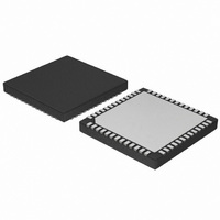
IC MODEM PLC 50/60MHZ 52QFN
Manufacturer
ON Semiconductor
Datasheet
1.AMIS49587C5871RG.pdf
(55 pages)
Specifications of AMIS49587C5872G
Baud Rates
Selectable
Interface
SCI
Voltage - Supply
3 V ~ 3.6 V
Mounting Type
Surface Mount
Package / Case
52-TQFN Exposed Pad
Maximum Operating Temperature
+ 80 C
Minimum Operating Temperature
- 40 C
Modulation Type
.
Mounting Style
SMD/SMT
Operating Supply Voltage
+ 3 V to 3.6 V
Number Of Transmitters
1
Power Supply Requirement
Single
Package Type
QFN EP
Operating Temperature Classification
Commercial
Mounting
Surface Mount
Pin Count
52
Operating Temperature (min)
-40C
Dual Supply Voltage (typ)
Not RequiredV
Dual Supply Voltage (max)
Not RequiredV
Dual Supply Voltage (min)
Not RequiredV
Lead Free Status / RoHS Status
Lead free / RoHS Compliant
Data Format
-
Lead Free Status / Rohs Status
Compliant


4.1.4 Receiver External Parameters: Pin RX_IN, RX_OUT, REF_OUT
9. Input at RX_IN, no other external components.
10. Characterization data only. Not tested in production.
11. A sinusoidal signal of 10 kHz and 100 mVpp is injected between VDDA and VSSA. The signal level at the differential LPF_OUT and
12. A sinusoidal signal of 50 Hz and 100 mVpp is injected between VDDA and VSSA. The signal level at the differential LPF_OUT output is
13. These parameters will be tested in production with an input signal of 95 kHz and 1 Vp by reading out the digital samples at the point AD_OUT
The receive LPF filter + AGC + low noise amplifier must have a frequency characteristic between the limits listed below. The
absolute output level depends on the operating condition. In production the measurement will be done for relative output levels
where the 0 dB reference value is measured at 50 kHz with a signal amplitude of 100 mV.
Table 12. RECEIVER EXTERNAL PARAMETERS: Pin RX_IN, RX_OUT, REF_OUT
Input offset voltage 42 dB
Input offset voltage 0 dB
Max. peak input voltage
(corresponding to 62.5% of the SD
full scale)
Input referred noise of the analog
receiver path
Input leakage current of receiver
input
Max. current delivered by REF_OUT
Power supply rejection ratio of the
receiver input section
AGC gain step
AGC range
Analog ground reference output
voltage
Signal to noise ratio at 62.5% of the
SD full scale
Clipping level at the output of the
gain stage (RX_OUT)
Table 13. RECEIVER FREQUENCY CHARACTERISTICS
REF_OUT output is measured to determine the parameter.
measured to determine the parameter.
with the default settings of T_RX_MOD[7], SDMOD_TYP, DEC_TYP, and COR_F_ENA. The AGC gain is switched to 0 dB.
Frequency (kHz)
Parameter
1000
2000
130
165
330
660
10
95
AGC gain = 42 dB
AGC gain = 0 dB
AGC gain = 0 dB (Note 9)
AGC gain = 42 dB
(Notes 9 and 10)
AGC gain = 42 dB (Note 11)
AGC gain = 42 dB (Note 12)
(Notes 9 and 13)
Test Conditions
--0.5
--1.3
--4.5
Min
http://onsemi.com
Attenuation
13
PSRR
I
V
V
V
Max_REF_OUT
V
SN
CLIP_AGC_IN
V
OFFS_RX_IN
OFFS_RX_IN
AGC
I
MAX_RX_IN
NF
AGC
Symbol
LE_RX_IN
REF_OUT
AD_OUT
RX_IN
LPF_OUT
range
step
--18.0
--36.0
Max
--2.0
--3.0
--50
--55
0.5
0.5
--300
0.85
39.9
1.52
1.15
Min
5.7
--1
10
35
54
Typ
Unit
dB
dB
dB
dB
dB
dB
dB
dB
Max
1.15
44.1
1.78
1.65
150
300
6.3
50
5
1
nV/√Hz
Unit
mV
mV
mA
V
mA
dB
dB
dB
dB
Vp
V
p
Related parts for AMIS49587C5872G
Image
Part Number
Description
Manufacturer
Datasheet
Request
R

Part Number:
Description:
ON Semiconductor [VOLTAGE REGULATOR]
Manufacturer:
ON Semiconductor
Datasheet:
Part Number:
Description:
357-036-542-201 CARDEDGE 36POS DL .156 BLK LOPRO
Manufacturer:
ON Semiconductor
Datasheet:
Part Number:
Description:
357-036-542-201 CARDEDGE 36POS DL .156 BLK LOPRO
Manufacturer:
ON Semiconductor
Datasheet:
Part Number:
Description:
357-036-542-201 CARDEDGE 36POS DL .156 BLK LOPRO
Manufacturer:
ON Semiconductor
Datasheet:
Part Number:
Description:
357-036-542-201 CARDEDGE 36POS DL .156 BLK LOPRO
Manufacturer:
ON Semiconductor
Datasheet:
Part Number:
Description:
357-036-542-201 CARDEDGE 36POS DL .156 BLK LOPRO
Manufacturer:
ON Semiconductor
Datasheet:
Part Number:
Description:
357-036-542-201 CARDEDGE 36POS DL .156 BLK LOPRO
Manufacturer:
ON Semiconductor
Datasheet:
Part Number:
Description:
357-036-542-201 CARDEDGE 36POS DL .156 BLK LOPRO
Manufacturer:
ON Semiconductor
Datasheet:
Part Number:
Description:
357-036-542-201 CARDEDGE 36POS DL .156 BLK LOPRO
Manufacturer:
ON Semiconductor
Datasheet:
Part Number:
Description:
357-036-542-201 CARDEDGE 36POS DL .156 BLK LOPRO
Manufacturer:
ON Semiconductor
Datasheet:
Part Number:
Description:
357-036-542-201 CARDEDGE 36POS DL .156 BLK LOPRO
Manufacturer:
ON Semiconductor
Datasheet:
Part Number:
Description:
Manufacturer:
ON Semiconductor
Datasheet:
Part Number:
Description:
Manufacturer:
ON Semiconductor
Datasheet:
Part Number:
Description:
Manufacturer:
ON Semiconductor
Datasheet: