AD693AQ Analog Devices Inc, AD693AQ Datasheet - Page 12
AD693AQ
Manufacturer Part Number
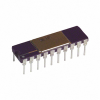
AD693AQ
Description
IC TRANSMITTER 4-20MA 20-CDIP
Manufacturer
Analog Devices Inc
Type
Signal Conditionerr
Datasheet
1.AD693AQ.pdf
(12 pages)
Specifications of AD693AQ
Rohs Status
RoHS non-compliant
Input Type
Voltage
Output Type
Voltage
Interface
3-Wire
Current - Supply
20mA
Mounting Type
Through Hole
Package / Case
20-CDIP (0.300", 7.62mm)
Supply Voltage Range
12V To 36V
Operating Temperature Range
-40°C To +85°C
Digital Ic Case Style
DIP
No. Of Pins
20
Svhc
No SVHC (18-Jun-2010)
Operating Temperature Max
85°C
Operating
RoHS Compliant
Converter Type
Voltage to Current
Current, Output
+25 mA (Typ.)
Current, Quiescent Supply
+500 uA (Typ.)
Package Type
Cerdip
Temperature, Operating, Maximum
85 °C
Temperature, Operating, Minimum
-40 °C
Voltage, Operating
+12 V (Min.)
No. Of Amplifiers
5
Input Offset Voltage
200µV
Cmrr
90dB
Supply Current
500µA
Amplifier Case Style
DIP
Rohs Compliant
No
Ic Function
Sensor Transmitter
Amplifier Type
Current
Base Number
693
Lead Free Status / RoHS Status
Available stocks
Company
Part Number
Manufacturer
Quantity
Price
Company:

Part Number:
AD693AQ
Manufacturer:
TOSHIBA
Quantity:
101
Part Number:
AD693AQ
Manufacturer:
ADI/亚德诺
Quantity:
20 000


AD693
and an input common-mode voltage of 3.1 V. The expressions
below calculate errors due to deviations from these nominal
conditions.
The total error at zero consists only of offset errors. The total
error at full scale consists of the offset errors plus the span
errors. Adding the above errors in this manner may result in an
error as large as 0.8% of full scale, however, as a rule, the
AD693 performs better as the span and offset errors do not tend
to add worst case. The specification “Total Unadjusted Error,”
(TUE), reflects this and gives the maximum error as a % of full
scale for any point in the transfer function when the device is
operated in one of its preset spans, with no external trims. The
TUE is less than the error you would get by adding the span
and offset errors worst case.
Thus, an alternative way of calculating the total error is to start
with the TUE and add to it those errors that result from
operation of the AD693 with a load resistance, loop supply
voltage, or common-mode input voltage different than specified.
(See Example 1 below.)
ERROR BUDGET FOR SPANS LESS THAN 30 mV
An accommodation must be made to include the input voltage
offset of the signal amplifier when the span is adjusted to less
than 30 mV. The TUE and the Zero Current Error include the
input offset voltage contribution of the signal amplifier in a gain
of 2. As the input offset voltage is multiplied by the gain of the
signal amplifier, one must include the additional error when the
signal amplifier is set to gains greater than 2.
For example, the 300K span thermocouple application discussed
previously requires a 12.207 mV input span; the signal amplifier
must be adjusted to a gain of approximately 5. The loop trans-
conductance is now 1.333 A/V, (5 0.2666 A/V). Calculate the
total error by substituting the new values for the transconductance
and span into the equations in Table III as was done in Example
I. The error contribution due to V
2
V
OS
is already included in the TUE and the Zero Current
20-Lead Side Brazed Ceramic DIP
D-20
OS
is 5
V
OS
, however, since
20-Terminal Leadless Chip Carrier
Dimensions shown in inches and (mm).
OUTLINE DIMENSIONS
E-20A
–12–
Error it is necessary to add an error of only (5 – 2) V
error budget. Note that span error may by reduced to zero with
the span trim, leaving only the offset and nonlinearity of the
AD693.
EXAMPLE I
The AD693 is configured as a 4-20mA loop powered transmitter
with a 60 mV FS input. The inputs are driven by a differential
voltage at 2 V common mode with a 300
resistance. A 24 V loop supply is used with a 500
resistance. (See Table IV below.)
Trimming the offset and span for your application will remove
all span and offset errors except the nonlinearity of the AD693.
OFFSET ERRORS
I
PSRR
CMRR CMRR = 30 V/V; |2 V –3.1 V|
IOS
Total Additional Error at 4 mA
As % of full scale; (39.5 V
SPAN ERRORS
X
X
X
I
X
Total Additional Span Error at Full Scale
Total Additional Error at Full Scale;
As % of Full Scale; (113.5 V
New Total Unadjusted Error @ FS;
Z
DIFF
SE
PSRR
CMRR
NL
Already included in the TUE spec .
PSRR = 5.6 V/V; ( 24 V – 24 V| + [ 500
V
R
V
IOS = 3 nA, R
Already included in the TUE spec
PSRR = 5.6 V/V; (|500
R
X
V
V
I
from Figure 2)
Already included in the TUE
DIFF
LOOP
L
CM
L
CM
SPAN
CMRR
= 500
= 500 , I
/ + In = 2
= 2 V
= 2 V, V
= 24 V
= +60 mV; 300
= 0.06%/V; |2 V – 3. 1 V|
I
Z
SPAN
S
= 4 mA
S
= 16 mA
= 300 ; 300
= 60 mV
0.2666 A/V)/20 mA
0.2666A V)/20 mA
Table IV. Example 1
2
– 250 |
OFFSET
20-Lead Cerdip
20 nA
TUE
3 nA =
+
30 V/V =
+
60 mV
Q-20
ADDITIONAL
SPAN
16 mA)
100% =
= 39.5 V + 74.0 V =
100% =
– 250
0.06%/V =
5.6 V/V =
= 0.5% +0.151% =
4 mA )
balanced source
5.6 V/V =5.6 V
metering
OS
0.0 V
33.0 V
0.9 V
0.053 % of FS
0.0 V
22.4 V
39.6 V
12.0 V
0.0 V
113.5 V
0.151% of FS
0.651% of FS
REV. A
to the
39.5 V
74.0 V
Related parts for AD693AQ
Image
Part Number
Description
Manufacturer
Datasheet
Request
R

Part Number:
Description:
±1.7g Dual-Axis IMEMS Accelerometer Evaluation Board
Manufacturer:
Analog Devices Inc
Datasheet:

Part Number:
Description:
Inertial Sensor Evaluation System
Manufacturer:
Analog Devices Inc
Datasheet:
Part Number:
Description:
Manufacturer:
Analog Devices Inc
Datasheet:
Part Number:
Description:
Manufacturer:
Analog Devices Inc
Datasheet:
Part Number:
Description:
Manufacturer:
Analog Devices Inc
Datasheet:
Part Number:
Description:
Manufacturer:
Analog Devices Inc
Datasheet:
Part Number:
Description:
Manufacturer:
Analog Devices Inc
Datasheet:
Part Number:
Description:
Manufacturer:
Analog Devices Inc
Datasheet:
Part Number:
Description:
Manufacturer:
Analog Devices Inc
Datasheet:
Part Number:
Description:
Manufacturer:
Analog Devices Inc
Datasheet:
Part Number:
Description:
Manufacturer:
Analog Devices Inc
Datasheet:
Part Number:
Description:
Manufacturer:
Analog Devices Inc
Datasheet:
Part Number:
Description:
Manufacturer:
Analog Devices Inc
Datasheet: