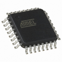
QT60168C-ASG Atmel, QT60168C-ASG Datasheet - Page 42

QT60168C-ASG
Manufacturer Part Number
QT60168C-ASG
Description
IC TOUCH SENSOR 16KEY 32TQFP
Manufacturer
Atmel
Series
QMatrix™, QProx™r
Type
Capacitiver
Specifications of QT60168C-ASG
Number Of Inputs/keys
16 Key
Resolution (bits)
9, 11 b
Data Interface
Serial, SPI™
Voltage - Supply
3 V ~ 5 V
Current - Supply
25mA
Operating Temperature
-40°C ~ 105°C
Mounting Type
Surface Mount
Package / Case
32-TQFP, 32-VQFP
Output Type
*
Interface
*
Input Type
*
For Use With
427-1087 - BOARD EVAL QT60248-AS QMATRIX
Lead Free Status / RoHS Status
Lead free / RoHS Compliant
Available stocks
Company
Part Number
Manufacturer
Quantity
Price
Company:
Part Number:
QT60168C-ASG
Manufacturer:
Atmel
Quantity:
5 323
10620D–AT42–04/09
Mutual-capacitance Zero-dimensional Sensors
4.3
4.3.1
4.3.2
4-10
Non-Planar Construction
Introduction
Flooded-X Two-layer Method
It is often desirable to form electrodes on the inner surface of a panel that is not part of the main
capacitive touch circuit board. This technique can be used with a mutual-capacitance type sensor,
typically using a spring as part of the sensor (see
other methods are possible (see
little effect on the field distribution until a touch is made, at which point a percentage of the field is
deflected through the panel vertically.
The methods for interconnection are tightly coupled with the method of construction. The rules for the
interconnecting traces are identical to those already described in
page
traces is no longer near to touch.
The flooded-X two-layer method distributes the X and Y electrodes across two layers of a substrate. This
style has some great advantages in terms of sensitivity for small keys, and has some good intrinsic noise
rejecting capabilities. Another useful property is that because the X electrode completely shields the Y
electrode from behind, the sensor is not touch-sensitive from behind. The field behavior is similar to that
mentioned above.
Figure 4-10. Flooded-X Two-layer Method
4-7. However, some of the constraints can be relaxed because the substrate used to route the
2 mm
4 mm Minimum
Substrate
Section 4.3.2
Grid Infill, 4 mm
Where Possible
0.1 – 0.5 mm Wide,
Subject To RC
Time Constant
Front Panel
Y (Nearest
To Touch)
X Flood
and
Section 4.3.3 “Spring Method” on page
Section 4.3.4 on page
Substrate
Less Than 4 mm
Open Spaces
Section 4.2.4 “Interconnection” on
4-13). The overlying panel has
Touch Sensors Design Guide
t2,Er2
t1,Er1
4-12), although


