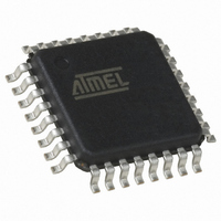
QT60168C-ASG Atmel, QT60168C-ASG Datasheet - Page 58

QT60168C-ASG
Manufacturer Part Number
QT60168C-ASG
Description
IC TOUCH SENSOR 16KEY 32TQFP
Manufacturer
Atmel
Series
QMatrix™, QProx™r
Type
Capacitiver
Specifications of QT60168C-ASG
Number Of Inputs/keys
16 Key
Resolution (bits)
9, 11 b
Data Interface
Serial, SPI™
Voltage - Supply
3 V ~ 5 V
Current - Supply
25mA
Operating Temperature
-40°C ~ 105°C
Mounting Type
Surface Mount
Package / Case
32-TQFP, 32-VQFP
Output Type
*
Interface
*
Input Type
*
For Use With
427-1087 - BOARD EVAL QT60248-AS QMATRIX
Lead Free Status / RoHS Status
Lead free / RoHS Compliant
Available stocks
Company
Part Number
Manufacturer
Quantity
Price
Company:
Part Number:
QT60168C-ASG
Manufacturer:
Atmel
Quantity:
5 323
10620D–AT42–04/09
Mutual-capacitance One-dimensional Sensors
6.3.2.2
6-4
Wheel
The sensor design for a wheel is essentially the same as that for the slider, but the array of keys are
arranged in a circular form (see
wheels from 15 mm to 21 mm in diameter that are constructed with at least 6 keys. Note that the X
fingers taper to Y
diameter of the wheel.
As with the slider, you will need to calculate the number of X fingers for the wheel. However, as there is
no end border, X
has been calculated is distributed equally across the X fingers.
Figure 6-2.
To design the wheel:
1. Decide on the diameter (D) of the wheel (15 mm to 21 mm).
2. Check that the outer arc (W) of each key in the wheel is between 6 and 8 mm:
If W is < 6 mm, then consider doing one of the following:
– Break the wheel into fewer keys
– Make the diameter of the wheel larger
If W is > 8 mm, then consider doing one of the following:
– Break the wheel into more keys (if the controller supports more keys)
– Make the diameter of the wheel smaller
– Use a resistively interpolated design to artificially break the wheel into smaller pieces
(see
X fingers
taper to
Y
(
Y
width
width
Section 6.4 “Typical Resistively Interpolated Method” on page
One-layer Small Wheel (Spatially Interpolated)
= 0.1–0.5 mm)
X5
X6
W = D / keys) - Y
border
Y
width
T/2 Gap
around Y
is not calculated and any unallocated width remaining after the number of fingers
or slightly greater (not sharp points), and this tapering determines the inner
Figure
X7
X4
width
6-2) and there is no end border. This design can be used for
Between Xs
Y
width
T
T
Gap
X0
X3
³ T
X electrodes require a jumper or via to
connect the
6-10)
W (6–8 mm)
Touch Sensors Design Guide
X2
X1
two isolated X regions
.


