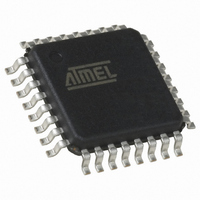
QT60168C-ASG Atmel, QT60168C-ASG Datasheet - Page 48

QT60168C-ASG
Manufacturer Part Number
QT60168C-ASG
Description
IC TOUCH SENSOR 16KEY 32TQFP
Manufacturer
Atmel
Series
QMatrix™, QProx™r
Type
Capacitiver
Specifications of QT60168C-ASG
Number Of Inputs/keys
16 Key
Resolution (bits)
9, 11 b
Data Interface
Serial, SPI™
Voltage - Supply
3 V ~ 5 V
Current - Supply
25mA
Operating Temperature
-40°C ~ 105°C
Mounting Type
Surface Mount
Package / Case
32-TQFP, 32-VQFP
Output Type
*
Interface
*
Input Type
*
For Use With
427-1087 - BOARD EVAL QT60248-AS QMATRIX
Lead Free Status / RoHS Status
Lead free / RoHS Compliant
Available stocks
Company
Part Number
Manufacturer
Quantity
Price
Company:
Part Number:
QT60168C-ASG
Manufacturer:
Atmel
Quantity:
5 323
10620D–AT42–04/09
Self-capacitance One-dimensional Sensors
5.2.3
5.2.4
5.2.5
5-2
Hand Shadow Effect
Floating Conductive Items
Conductive Paints
When a sensor is particularly large in proportion to a hand, it is possible for a false touch to be detected
from the hand as it is held over the sensor, rather than from the user’s finger. This is known as the hand
shadow effect (see
Figure 5-1.
This effect presents a particular problem for large sliders or wheels that use the self-capacitance style of
electrode. These electrodes are generally scanned so that all the channels are measured at the same
time, which makes all the channels equally touch sensitive.
The considerations for the use of floating conductive items described in
Conductive Items” on page 3-6
The considerations for the use of conductive paints described in
page 3-7
Note that wheels and sliders, in particular, can be badly affected by conductive paints and finishes. The
reason for this is that the calculation of the touch position relies on the difference in signal between the
various channels, and the conductive paint has a tendency to make the channels cross-couple together.
The result is a considerable degradation of the resolution of the sensor.
If this is not possible, and the connecting traces have to be routed on the same layer as the electrodes
themselves, always escape the traces as quickly as possible out of the touch area; then regroup the
three traces for their path to the sensor chip. It can be useful in some cases to run a thin ground trace
alongside these escaping traces to desensitize them to touch. Note that some experimentation is
usually necessary.
apply.
Hand Shadow Effect
Touch here
Figure
5-1).
apply.
Sensor
Section 3.2.7 “Conductive Paints” on
Influence here despite
no panel contact
Touch Sensors Design Guide
Section 3.2.6 “Floating


