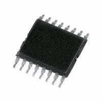
PCA9541PW/01,112 NXP Semiconductors, PCA9541PW/01,112 Datasheet - Page 8

PCA9541PW/01,112
Manufacturer Part Number
PCA9541PW/01,112
Description
IC I2C 2:1 SELECTOR 16-TSSOP
Manufacturer
NXP Semiconductors
Datasheet
1.PCA9541BS03118.pdf
(41 pages)
Specifications of PCA9541PW/01,112
Applications
2-Channel I²C Multiplexer
Interface
I²C, SMBus
Voltage - Supply
2.3 V ~ 5.5 V
Package / Case
16-TSSOP
Mounting Type
Surface Mount
For Use With
568-3615 - DEMO BOARD I2C
Lead Free Status / RoHS Status
Lead free / RoHS Compliant
Other names
568-1043-5
935273297112
PCA9541PW/01
935273297112
PCA9541PW/01
NXP Semiconductors
PCA9541_7
Product data sheet
8.3 Interrupt Enable and Control registers description
Only the 2 least significant bits are affected by the AI flag.
Unused bits must be programmed with zeros. Any command code (write operation)
different from ‘000AI 0000’, ‘000AI 0001’, and ‘000AI 0010’ will not be acknowledged. At
power-up, this register defaults to all zeros.
Table 4.
Each system master controls its own set of registers, however they can also read specific
bits from the other system master.
When a master seeks control of the bus by connecting its I
PCA9541 downstream channel, it has to write to the CONTROL register (Reg#01).
Bits MYBUS and BUSON allow the master to take control of the bus.
The MYBUS and the NMYBUS bits determine which master has control of the bus.
Table 9
master can take control of the bus when it wants regardless of whether the other master is
using it or not.
The BUSON and the NBUSON bits determine whether the upstream bus is connected or
disconnected to/from the downstream bus.
connected or disconnected.
Internally, the state machine does the following:
B1
0
0
1
1
Fig 7.
•
•
During a write operation, the PCA9541 will acknowledge bytes sent to the IE and
CONTROL registers, but will not acknowledge a byte sent to the Interrupt Status
Register since it is a read-only register. The 2 LSBs of the Command Code do not roll
over to 00b but stay at 10b.
If the combination of the BUSON and the NBUSON bits causes the upstream to be
disconnected from the downstream bus, then that is done. So in this case, the values
of the MYBUS and the NMYBUS do not matter.
CONTROL
ISTAT
IE
SDA_MST0
SCL_MST0
MASTER 0
explains which master gets control of the bus and how. There is no arbitration. Any
B0
0
1
0
1
Internal register map
Command Code register
REG#00
REG#01
REG#10
Register name
IE
CONTROL
ISTAT
not allowed
Rev. 07 — 2 July 2009
2-to-1 I
CONTROL 0
ISTAT 0
2
C-bus master selector with interrupt logic and reset
IE 0
Type
R/W
R/W
R only
PCA9541
Table 10
Register function
interrupt enable
control switch
interrupt status
CONTROL 1
ISTAT 1
explains when the upstream bus is
IE 1
002aab392
2
C-bus channel to the
REG#00
REG#01
REG#10
PCA9541
© NXP B.V. 2009. All rights reserved.
SCL_MST1
SDA_MST1
MASTER 1
CONTROL
ISTAT
IE
8 of 41


