2469-63-54-0-AFB-1-M YOKOGAWA, 2469-63-54-0-AFB-1-M Datasheet
2469-63-54-0-AFB-1-M
Specifications of 2469-63-54-0-AFB-1-M


Related parts for 2469-63-54-0-AFB-1-M

2469-63-54-0-AFB-1-M Summary of contents
Page 1
... YOKOGAWA POWER TRANSDUCER CATALOG ...
Page 2
... Miniature Plastic Case transducers available in foot mount style as well as DIN rail mount. With this wide array, YCA can surely meet most any power transducer application you may have. Since our establishment in the United States in 1957, Yokogawa Corporation of America (YCA) has become a leading North American manufacturer and supplier of Test and Measurement, Field ...
Page 3
... PLC’s, SCADA systems, Energy Management Systems, etc. Usually, 0.5% accuracy is adequate for most industrial monitoring needs. Our 2469 meets this requirement. Most power utility applications, however, require a higher level of accuracy. Our 2489 series, with 0.2% accuracy, is recommended for such applications. The plastic case power transducers (2370 & ...
Page 4
... GENERAL The 2469 and 2489 AC Average Current transducers produce an analog DC signal output corresponding to the average value of the AC input. The true RMS versions always require external power and produce an analog DC output corresponding to the true RMS value of the input signal. 2) SPECIFICATIONS Model # Input Current ...
Page 5
... (1) 4) ORDER FORMAT 2469 / 89 Model# (1) Transducer function 21 Average current 2469 Avg. current 2489 31 True RMS current 5) CONNECTION DIAGRAMS FOR CT INPUT LINE OUTPUT - + LOAD 246921 248921 SELF POWERED 6) MOUNTING AND OUTLINE DIMENSIONS: (77.15) ➤ ➤ 3.037 (88.9) ➤ 3.500 (10.1) ➤ 3.976 ...
Page 6
... GENERAL The 2469 and 2489 AC Average Voltage transducers produce an analog DC signal output corresponding to the average value of the AC input. The true RMS versions always require external power and produce an analog DC output corresponding to the true RMS value of the input signal. 2) SPECIFICATIONS Model # Input Voltage ...
Page 7
... (1) 4) ORDER FORMAT 2469 / 89 Model# (1) Transducer function 22 Average Voltage 2469 Avg. Voltage 2489 32 True RMS Voltage 5) CONNECTION DIAGRAMS FOR PT INPUT LINE OUTPUT - + LOAD 246922 248922 SELF POWERED 6) MOUNTING AND OUTLINE DIMENSIONS: (77.15) ➤ ➤ 3.037 (88.9) ➤ 3.500 (10.1) ➤ 3.976 ...
Page 8
... GENERAL The 2469 series isolator provides an isolated analog output proportional to the DC voltage or current input. Standard inputs are 50mVDC and 1 mADC. Auxiliary power is required to power the isolator. Other DC inputs and power options are available on special order from Yokogawa. 2) SPECIFICATIONS Model # Input signal ranges ...
Page 9
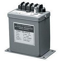
... ORDER FORMAT 2469 Model# (1) Transducer function 11 DC Voltage input 2469 12 DC Current input Consult factory for other input / output / power-up options 5) CONNECTION DIAGRAMS 6) MOUNTING AND OUTLINE DIMENSIONS: ➤ (120.65) ➤ ➤ (2) (3) ( (2) Input (3) Output 001 0-50 mVDC AFA 101 0-1 mADC ...
Page 10
... GENERAL The 2469 and 2489 AC Watt transducers produce an analog output equal to the Watts measured by the input. The typical calibration is 500 Watts / element for 120V and 5A AC transformer secondary inputs. 2) SPECIFICATIONS Model # Current input / range Current input over range capability Current input burden ...
Page 11
... (1) 4) ORDER FORMAT 2469 / 89 Model# (1) Transducer function 2469 51 Watt 1P2W (1 Element) 2489 52 Watt 3P3W (1 ⁄ Element Watt 3P3W (2 Element) 54 Watt 3P4W (2 1 ⁄ Element Watt 3P4W (3 Element) *Not UL 5) CONNECTION DIAGRAMS WITH PT AND CT INPUTS LINE 246951 OUTPUT - + 248951 LOAD - + AUX POWER ...
Page 12
... GENERAL The 2469 and 2489 AC VAR transducers produce an analog output equal to the VARS measured by the input. The typical calibration is 500 VARS / element for 120V and 5A AC transformer secondary inputs. 2) SPECIFICATIONS Model # Current input / range Current input over range capability Current input burden ...
Page 13
... (1) 4) ORDER FORMAT 2469 / 89 Model# (1) Transducer function 2469 61 VAR 1P2W (1 Element) 2489 62 VAR 3P3W (1 ⁄ Element VAR 3P3W (2 Element) 64 VAR 3P4W (2 1 ⁄ Element VAR 3P4W (3 Element) *Not UL 5) CONNECTION DIAGRAMS WITH PT AND CT INPUTS LINE 246961 OUTPUT - + 248961 LOAD - + AUX POWER ...
Page 14
... GENERAL The 2469 and 2489 combined WATT/VAR transducers produce an analog output equal to the WATTS and VARS measured by the input. 2) SPECIFICATIONS Model # Current input / range Current input over range capability Current input burden Voltage inputs and range: Input powered range Auxiliary powered range ...
Page 15
... ORDER FORMAT 2469 / 89 Model# (1) Transducer function 2469 41 W/V 1P2W (1 Element) 2489 42 W/V 3P3W (1 ⁄ Element W/V 3P3W (2 Element) 44 W/V 3P4W (2 ⁄ Element W/V 3P4W (3 Element) 5) CONNECTION DIAGRAMS WITH PT AND CT INPUTS DC OUTPUT LINE L1 L2 246941 - + + 248941 LOAD - + AUX POWER (OPTIONAL) 1P2W (1 element) ...
Page 16
... GENERAL The 2469 and 2489 Power Factor transducers have an analog output corresponding to 1- Cosine of the phase angle of the input current relative to the input voltage signal. The analog output will indicate lead- ing or lagging Power Factor by its direction from center which would be either 12mA based on output selection ...
Page 17
... ORDER FORMAT 2469 / 89 Model# (1) Transducer function (2) Input 2469 71 PF-Single Phase 53 2489 73 PF-3P3W balanced 54 74 PF-3P4W balanced CONNECTION DIAGRAMS WITH PT AND CT INPUTS LINE L1 DC OUTPUT - + LOAD - + AUX POWER (OPTIONAL) 246971 248971 Single phase 6) MOUNTING AND OUTLINE DIMENSIONS: (111.6) ➤ 4.394 (120.65) ➤ ...
Page 18
... GENERAL The 2469 and 2489 Phase Angle transducers have an analog output corresponding to the phase angle of the input current relative to the input voltage signal. The analog output will indicate leading or lagging Phase Angle by its direction from center which would be either 12mA based on output selection. ...
Page 19
... ORDER FORMAT 2469 / 89 Model# (1) Transducer function (2) Input 2469 76 PA-Single Phase 53 2489 77 PA-3P3W balanced 54 78 PA-3P4W balanced CONNECTION DIAGRAMS WITH PT AND CT INPUTS LINE L1 DC OUTPUT - + LOAD - + AUX POWER (OPTIONAL) 246976 248976 Single phase 6) MOUNTING AND OUTLINE DIMENSIONS: (111.6) ➤ 4.394 (120.65) ➤ ...
Page 20
... GENERAL The 2469 and 2489 Frequency transducers have an analog output corresponding to the frequency of the AC input voltage. These transducers are capable of high accuracy measurement over various frequency ranges. 2) SPECIFICATIONS Model # Voltage inputs and range: Input powered range Auxiliary powered range Voltage input burden Rated outputs Accuracy: ± ...
Page 21
... ORDER FORMAT 2469 / 89 Model# (1) Transducer function 2469 81 ± 0.5 Hz deviation 2489 82 ± deviation 83 ± deviation 84 ± deviation 84 ± deviation 85 ± deviation 86 ± deviation 5) CONNECTION DIAGRAMS OUTPUT 6) MOUNTING AND OUTLINE DIMENSIONS: (111.6) ➤ 4.394 (120.65) ➤ 4.750 ➤ 5.236 (1) (2) (3) (4) ( (2) Input ...
Page 22
... Yokogawa 2489 series transducers are designed for reliable and repeatable operation over a wide range of conditions at the highest attainable accuracy. Recently, we performed a series of tests on our transducers in a Thermotron test chamber with a Rotek 800AE calibrator, Yokogawa 2558 AC standard and 7562 digital multi- meter. We plotted outputs at various inputs, temperatures, and power factors. These charts are a sampling of data from these tests and consistently demonstrate a high level of accuracy and performance over the full range of conditions ...
Page 23
CIRCUIT CONFIGURATIONS AND TYPICAL POWER MEASUREMENT APPLICATIONS Circuit configuration Common Power Distribution systems 1P2W 1 Element 120/240V 1P3W 1 1 ⁄ Element 120/240V 2 3P3W 2 Element 240 and 480V ...
Page 24
Accuracy The ratio of the error to a standard or true value and expressed as a percent. Ampere Unit of electrical current or rate of flow of electrons. One volt across one ohm of resistance ...
Page 25
Neutral or neutral conductor The common return path for current from the load to the source in AC circuits. Frequently connected to ground. Ohm One ohm is a unit of electrical resistance equal to that ...
Page 26
GENERAL The 2371-2378 and 2461-2468 series of power transducers combine high performance with compact size. Most of these transducers are self powered except isolators and True RMS Amps and Volts which require auxiliary power. Accuracy of ...
Page 27
GENERAL SPECIFICATIONS Overrange capability Dielectric strength between: Current input: 1) Input terminals & case - 2600VAC for 1 minute 1000% of rated input for 5 sec. 2) Input & output terminals - ...
Page 28
CONNECTION DIAGRAMS DC/DC isolator 2371 2461 SOURCE K AC voltage/ current k CT 2372 2373 2462 2463 LOAD SOURCE AUX POWER K AC voltage current 2374 A 2464 V LOAD OUTPUT SOURCE 1 2 Power/ Fuse Reactive ...
Page 29
CONNECTION DIAGRAMS (CONTINUED) SOURCE Fuse Power/ Reactive K K Power k k 2375 CT 2376 2465 237530 2466 237630 246530 LOAD 246630 SOURCE 237710 LOAD 246710 Phase Angle 2377 2467 SOURCE 1 ...
Page 30
MOUNTING DIMENSIONS AND TERMINAL BOARD LAYOUT: millimeters (inches) 55 (2.17") 125 (4.92") 6.5 ø6.5 Hole 2370 Series Mounting Side by Side (Caution) When putting 2 or more transducers side by side, separate ...
Page 31
... Other Catalogs Available . . . Power Series Plus The Power Series Plus digital switchboard meter was devel- oped by Yokogawa to provide customers with a versatile AC digital power meter. The heart of the meter is a programmable ASIC chip which allows us to combine a high accuracy meter with transducer output. ...
Page 32
... YOKOGAWA Yokogawa Corporation of America 2 Dart Road Newnan, GA 30265 770-253-7000 800-258-2552 FAX: 770-251-2088 BU-JAC-07E Represented by: ...