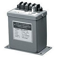
2469-63-54-0-AFB-1-M YOKOGAWA, 2469-63-54-0-AFB-1-M Datasheet - Page 25

2469-63-54-0-AFB-1-M
Manufacturer Part Number
2469-63-54-0-AFB-1-M
Description
63K2357
Manufacturer
YOKOGAWA
Datasheet
1.2489-63-54-0-AHF-1-0-M.pdf
(32 pages)
Specifications of 2469-63-54-0-AFB-1-M
Transducer Function
VAR 3P3W (2 Element)
Supply Voltage Min
100V
Supply Voltage Max
135V
Transducer Input Current Ac
5A
Frequency
60Hz
Supply Voltage
120VAC
Rohs Compliant
NA
P O W E R
T R A N S D U C E R
T E R M I N O L O G Y
Neutral or neutral conductor
The common return path for current from the load to the source in AC circuits. Frequently connected to ground.
Ohm
One ohm is a unit of electrical resistance equal to that of a conductor in which a current of one ampere is
produced by a potential of one volt across its terminals.
Output ripple
Expressed as percent of full scale or span and represents the magnitude of AC fluctuations in the DC output signal.
Overrange
The maximum input or output values above rated values.
Peak-to-Peak
Amplitude of an AC waveform from the positive to the negative peak value.
Phase
The number of separate voltage waves in an AC supply such as single phase or three phase.
Phase Angle
The angular difference in electrical degrees by which current leads voltage in a capacitive circuit or lags voltage
in an inductive circuit.
Polyphase
More than one phase conductor: such as a 3 phase 3 wire power circuit (3P3W).
Potential Transformer (PT)
An instrument transformer with primary winding connected in parallel with the circuit to be measured. Used to
step-up or step-down an AC voltage to a level that can be used for measurement or control purposes.
Potential Transformer ratio (PT ratio)
The ratio of primary voltage divided by the secondary voltage (ie, 14,400V : 120V = 120 : 1).
Power Factor
The Power Factor of any AC circuit is equal to the true power (watts) divided by the apparent power (volt-
amperes) which is equal to the cosine of the phase angle in circuits with sinusoidal waveforms.
Reading
The expected output value at a given input value.
Response time
In transducer terms, the time required after an abrupt change in input value for the output signal to reach 99%
of the new input. Response time is influenced by many factors and standardized test conditions should apply.
RMS
Abbreviation for root-mean-square. The value of AC current or voltage that will produce the same amount of
heat in a pure resistance as the corresponding value of DC.
Sine wave or sinusoidal wave
An alternating signal where instantaneous values vary as the sine of the peak value over a complete cycle.
Span
The difference between the low and high limits of a range (ie, 4-20mA has a span of 16mA).
Surge Withstand Capability test (SWC)
An oscillatory test wave applied to a transducer by a generator to simulate transient voltage conditions that could
be damaging to an unprotected component system.
Transducer
A device used for measurement purposes that accepts an electrical signal and outputs a low level DC signal that
is proportionate to the input.
True RMS
The definition is the same as RMS, except that it is a more precise method of measuring non-sinusoidal waveforms.
VAR (Volt-Ampere-Reactive)
A unit of reactive power as opposed to real power in Watts. Measured in VARS, KiloVARS, MegaVARS.
Volt
A unit of electromotive force. One volt equals the force required to produce one ampere of current to flow
through a resistance of one ohm.
Watt
A unit of real (effective) power measured in Watts, Kilowatts, Megawatts. Equals the product of Voltage, Current
and Power Factor (EI x PF = Watts) in a sinusoidal system.
Waveform
The graphic representation of the shape of an electromagnetic wave showing the variations in amplitude with
time.
23


