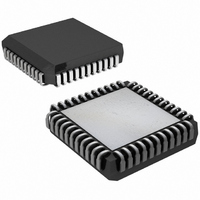
DS2151QB+ Maxim Integrated Products, DS2151QB+ Datasheet - Page 11

DS2151QB+
Manufacturer Part Number
DS2151QB+
Description
IC TXRX T1 1-CHIP 5V LP 44-PLCC
Manufacturer
Maxim Integrated Products
Datasheet
1.DS2151QB.pdf
(60 pages)
Specifications of DS2151QB+
Function
Single-Chip Transceiver
Interface
T1
Number Of Circuits
1
Voltage - Supply
4.75 V ~ 5.25 V
Current - Supply
65mA
Operating Temperature
0°C ~ 70°C
Mounting Type
Surface Mount
Package / Case
44-LCC, 44-PLCC
Includes
Alarm Detector and Generator, CSU Loop Codes Generator and Detector, DSX-1 and CSU Line Build-Outs Generator
Lead Free Status / RoHS Status
Lead free / RoHS Compliant
Power (watts)
-
RCR2: RECEIVE CONTROL REGISTER 2 (Address = 2C Hex)
(MSB)
RCS
SYMBOL
MOSCRF
RZBTSI
RD4YM
RSDW
FSBE
RSIO
RSM
RCS
RZBTSI
POSITION
RCR2.7
RCR2.6
RCR2.5
RCR2.4
RCR2.3
RCR2.2
RCR2.1
RCR2.0
RSDW
NAME AND DESCRIPTION
Receive Code Select.
0 = idle code (7F Hex)
1 = digital milliwatt code (1E/0B/0B/1E/9E/8B/8B/9E Hex)
Receive Side ZBTSI Enable.
0 = ZBTSI disabled
1 = ZBTSI enabled
RSYNC Double-Wide.
0 = do not pulse double-wide in signaling frames
1 = do pulse double-wide in signaling frames (Note: this bit
must be set to 0 when RCR2.4 = 1 or when RCR2.3 = 1.)
RSYNC Mode Select.
0 = frame mode (see the timing in Section 14)
1 = multiframe mode (see the timing in Section 14)
RSYNC I/O Select.
0 = RSYNC is an output
1 = RSYNC is an input (only valid if elastic store enabled)
(Note: this bit must be set to 0 when CCR1.2 = 0.)
Receive Side D4 Yellow Alarm Select.
0 = 0s in bit 2 of all channels
1 = a 1 in the S-bit position of frame 12
PCVCR Fs Bit Error Report Enable.
0 = do not report bit errors in Fs bit position; only Ft bit
position
1 = report bit errors in Fs bit position as well as Ft bit position
Multiframe Out of Sync Count Register Function Select.
0 = count errors in the framing bit position
1 = count the number of multiframes out of sync
RSM
11 of 60
RSIO
RD4YM
FSBE
MOSCRF
(LSB)


