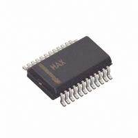
MAX9511CEG+ Maxim Integrated Products, MAX9511CEG+ Datasheet

MAX9511CEG+
Specifications of MAX9511CEG+
Related parts for MAX9511CEG+
MAX9511CEG+ Summary of contents
Page 1
... Bidirectional Level Translators for DDC Support ♦ Simultaneously Drives External Monitor/Projector and Docking Station without Analog RGB Switches—No Stub Reflections ♦ Eliminates External Components ♦ Small 24-Pin QSOP Package PART MAX9511CEG MAX9511CEG+ + Denotes a lead-free package. RED_IN GREEN_IN Applications BLUE_IN DDC_DATA_IN ...
Page 2
RGBHV Driver with EMI Suppression ABSOLUTE MAXIMUM RATINGS V to AGND............................................................-0. DGND ...............................................-0.3V to +6V DD1 DD2 DGND to AGND.....................................................-0.1V to +0.1V RED_IN, GREEN_IN, BLUE_IN to AGND.....-0. RED_OUT, GREEN_OUT, BLUE_OUT to ...
Page 3
RGBHV Driver with EMI Suppression ELECTRICAL CHARACTERISTICS (continued) = SHDN = DD1 DD2 values are +25°C.) A PARAMETER SYMBOL Slew Rate (Notes Settling Time ...
Page 4
RGBHV Driver with EMI Suppression ELECTRICAL CHARACTERISTICS (continued) = SHDN = DD1 DD2 values are +25°C.) A PARAMETER SYMBOL Rise/Fall Time Propagation Delay ...
Page 5
RGBHV Driver with EMI Suppression ( 150Ω to AGND DD1 DD2 L SMALL-SIGNAL BANDWIDTH vs. FREQUENCY vs 5kΩ RX ...
Page 6
RGBHV Driver with EMI Suppression ( 150Ω to AGND DD1 DD2 L SYNC PULSE RESPONSE INPUT 1V/div C = 47pF L OUTPUT C = 150pF L 1V/div C ...
Page 7
RGBHV Driver with EMI Suppression ( 150Ω to AGND DD1 DD2 L POWER-SUPPLY CURRENT vs. TEMPERATURE ( DD1 DD2 4.0 SHDN = V DD2 3.5 ...
Page 8
RGBHV Driver with EMI Suppression Block Diagram V CC MAX9511 R V ISENSE Y GREEN_IN -75Ω ISENSE Y RED_IN -75Ω ISENSE Y BLUE_IN -75Ω V DD1 SHDN DDC_DATA_IN R B ...
Page 9
RGBHV Driver with EMI Suppression VIDEO CONTROLLER I OUT CURRENT DAC Figure 1. Conventional Load-Detection Scheme VIDEO CONTROLLER I OUT REF CURRENT DAC Figure 2. Load-Detection Scheme with MAX9511 resistor to the input. This results in an equivalent imped- ance ...
Page 10
RGBHV Driver with EMI Suppression Vertical and Horizontal SYNC The MAX9511 has separate, noninverting, vertical and horizontal sync buffers. Both sync inputs can level-shift an input as low as 2. output. Both sync drivers have hysteresis at ...
Page 11
RGBHV Driver with EMI Suppression POWER- MANAGEMENT CIRCUIT 7 SHDN 8 DDC_DATA_IN 9 DDC_CLK_IN 10 H_SYNC_IN 11 V_SYNC_IN 4 RED_IN 37.5Ω 2 GREEN_IN 37.5Ω 5 BLUE_IN 37.5Ω 3, 20, 22, 24 Figure 4. Three Resolution Slew-Rate Control Figure 4 showcases ...
Page 12
RGBHV Driver with EMI Suppression POWER- MANAGEMENT CIRCUIT 7 SHDN 8 DDC_DATA_IN 9 DDC_CLK_IN 10 H_SYNC_IN 11 V_SYNC_IN 4 RED_IN 37.5Ω 2 GREEN_IN 37.5Ω 5 BLUE_IN 37.5Ω 3, 20, 22, 24 Figure 5. Slew-Rate Control with a Digital Potentiometer The ...
Page 13
RGBHV Driver with EMI Suppression The MAX9511 operates with a 4.5V to 5.5V power sup- ply for video (RGBHV), while DDC and SYNC operate from 2.3V to 3.6V and 4.5V to 5.5V supplies. SYNC Bandwidth-Limiting Capacitors The output impedance, R ...
Page 14
RGBHV Driver with EMI Suppression POWER- MANAGEMENT CIRCUIT 7 SHDN 8 DDC_DATA_IN 9 DDC_CLK_IN 10 H_SYNC_IN 11 V_SYNC_IN 4 RED_IN 37.5Ω 2 GREEN_IN 37.5Ω 5 BLUE_IN 37.5Ω 3, 20, 22 ______________________________________________________________________________________ 5V 2.3V TO 3.6V 5V 0.1µF* 0.1µF ...
Page 15
... Maxim cannot assume responsibility for use of any circuitry other than circuitry entirely embodied in a Maxim product. No circuit patent licenses are implied. Maxim reserves the right to change the circuitry and specifications without notice at any time. Maxim Integrated Products, 120 San Gabriel Drive, Sunnyvale, CA 94086 408-737-7600 ____________________ 15 © 2007 Maxim Integrated Products Package Information PACKAGE OUTLINE, QSOP .150" ...


