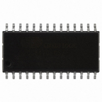
CS8420-CSZ Cirrus Logic Inc, CS8420-CSZ Datasheet - Page 83

CS8420-CSZ
Manufacturer Part Number
CS8420-CSZ
Description
IC SAMPLE RATE CONVERTER 28SOIC
Manufacturer
Cirrus Logic Inc
Type
Sample Rate Converterr
Specifications of CS8420-CSZ
Package / Case
28-SOIC
Applications
CD-R, DAT, DVD, MD, VTR
Mounting Type
Surface Mount
Operating Supply Voltage
5 V
Operating Temperature Range
- 10 C to + 70 C
Mounting Style
SMD/SMT
Resolution
17 bit to 24 bit
Control Interface
3 Wire, Serial
Supply Voltage Range
4.75V To 5.25V
Audio Ic Case Style
SOIC
No. Of Pins
28
Bandwidth
20kHz
Rohs Compliant
Yes
Audio Control Type
Volume
Dc
0841
Lead Free Status / RoHS Status
Lead free / RoHS Compliant
For Use With
598-1782 - EVALUATION BOARD FOR CS8420
Lead Free Status / Rohs Status
Lead free / RoHS Compliant
Other names
598-1125-5
Available stocks
Company
Part Number
Manufacturer
Quantity
Price
Company:
Part Number:
CS8420-CSZ
Manufacturer:
CIRRUS
Quantity:
319
Company:
Part Number:
CS8420-CSZ
Manufacturer:
CIRRUS
Quantity:
9 908
Part Number:
CS8420-CSZ
Manufacturer:
CIRRUS
Quantity:
20 000
Company:
Part Number:
CS8420-CSZ/D1
Manufacturer:
CIRRUS
Quantity:
378
Company:
Part Number:
CS8420-CSZR
Manufacturer:
NICHICON
Quantity:
4 200
DS245F4
.
15.1.2 Reserving the First 5 Bytes in the E Buffer
15.1.3 Serial Copy Management System (SCMS)
15.1.4 Channel Status Data E Buffer Access
D-to-E buffer transfers periodically overwrite the data stored in the E buffer. This can be a problem for
users who want to transmit certain channel status settings which are different from the incoming settings.
In this case, the user would have to superimpose his settings on the E buffer after every D-to-E overwrite.
To avoid this problem, the CS8420 has the capability of reserving the first 5 bytes of the E buffer for user
writes only. When this capability is in use, internal D-to-E buffer transfers will NOT affect the first 5 bytes
of the E buffer. Therefore, the user can set values in these first 5 E bytes once, and the settings will persist
until the next user change. This mode is enabled via the Channel Status Data Buffer Control register.
In Software mode, the CS8420 allows read/modify/write access to all the channel status bits. For Con-
sumer mode SCMS compliance, the host microcontroller needs to read and manipulate the Category
Code, Copy bit and L bit appropriately.
In Hardware mode, the SCMS protocol can be followed by either using the COPY and ORIG input pins,
or by using the C bit serial input pin. These options are documented in the Hardware mode section of this
data sheet (See
The E buffer is organized as 24 x 16-bit words. For each word the MS Byte is the A channel data, and the
LS Byte is the B channel data (see
There are two methods of accessing this memory, known as one-byte mode and two-byte mode. The de-
sired mode is selected via a control register bit.
“Hardware Modes” on page
Figure 40. Flowchart for Writing the E Buffer
E to F interrupt occurs
Return
Figure
Optionally set E to F inhibit
If set, clear E to F inhibit
Wait for E to F transfer
Clear D to E inhibit
37).
Set D to E inhibit
55)
Write E data
CS8420
83


