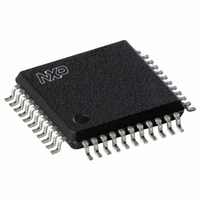
TEF6890H/V2,557 NXP Semiconductors, TEF6890H/V2,557 Datasheet - Page 10

TEF6890H/V2,557
Manufacturer Part Number
TEF6890H/V2,557
Description
IC RADIO SIGNAL PROC 44-QFP
Manufacturer
NXP Semiconductors
Type
Car Signal Processorr
Datasheet
1.TEF6890HV2557.pdf
(55 pages)
Specifications of TEF6890H/V2,557
Applications
Automotive Audio
Mounting Type
Surface Mount
Package / Case
44-MQFP, 44-PQFP
Lead Free Status / RoHS Status
Lead free / RoHS Compliant
Other names
935272793557
TEF6890H/V2
TEF6890H/V2
TEF6890H/V2
TEF6890H/V2
Available stocks
Company
Part Number
Manufacturer
Quantity
Price
Company:
Part Number:
TEF6890H/V2,557
Manufacturer:
NXP Semiconductors
Quantity:
10 000
Philips Semiconductors
7.6
The tone/volume control part consists of the following
stages:
The settings of all stages are controlled via the I
The stages input selector, loudness, volume/balance,
bass, and fader/output mute include the Audio Step
Interpolation (ASI) function. This minimizes pops by
smoothing the transitions in the audio signal during the
switching of the controls. The transition time of the ASI
function is programmable by I
7.6.1
The input selector selects one of four input sources:
7.6.2
The output of the input selector is fed into the loudness
circuit. Four different loudness curves can be selected via
the I
with a step size of 1 dB; see Figs 16 to 19.
7.6.3
The volume/balance control is used for volume setting and
also for balance adjustment. The control range of the
volume/balance control is between +20 and 59 dB in
steps of 1 dB.
The combination of loudness and volume/balance realizes
an overall control range of +20 to 79 dB.
2003 Oct 21
Input selector
Loudness control
Volume/balance control with muting
Treble control
Bass control
Fader and output mute
Beep generator
NAV input
Output mixer.
Two external stereo inputs (CD and TAPE)
One external mono input (PHONE)
One internal stereo input (AM/FM).
Car radio integrated signal processor
2
C-bus. The control range is between 0 and 20 dB
Tone/volume control
I
L
V
NPUT SELECTOR
OUDNESS
OLUME
/
BALANCE
2
C-bus in four steps.
2
C-bus.
10
7.6.4
The signal is then fed to the treble control stage. The
control range is between +14 and 14 dB in steps of 2 dB.
Figure 20 shows the control characteristic. Four different
filter frequencies can be selected.
7.6.5
The characteristic of the bass attenuation curves can be
set to shelve or band-pass. Four different frequencies can
be selected as centre frequency of the band-pass curve.
Figures 21 and 22 show the bass curves with a band-pass
filter frequency of 60 Hz. The control range is between
+14 and 14 dB in steps of 2 dB.
7.6.6
The four fader/mute blocks are located at the end of the
tone/volume chain. The control range of these attenuators
is 0 to 59 dB. The step size is:
7.6.7
The output mixer circuit can add an additional audio signal
to any of the four outputs together with the main signal or
instead of the main signal.
The additional signal can be generated internally by the
beep generator with four different audio frequencies or
applied to the NAV input, for instance a navigation voice
signal.
7.7
The RDS demodulator recovers and regenerates the
continuously transmitted RDS or RBDS data stream of the
multiplex signal (MPXRDS) and provides the signals clock
(RDCL), data (RDDA) and quality (RDQ) for external use.
The RDS demodulator uses the reference frequency
(75.4 kHz) from the tuner IC and does not need a crystal.
1 dB between 0 and 15 dB
2.5 dB between 15 and 45 dB
3 dB between 45 and 51 dB
4 dB between 51 and 59 dB.
RDS demodulator
T
B
F
MIXER
B
REBLE
ADER
ASS
EEP GENERATOR AND
/
MUTE
NAV
INPUT WITH OUTPUT
Product specification
TEF6890H


