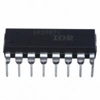
IR21571PBF International Rectifier, IR21571PBF Datasheet - Page 10

IR21571PBF
Manufacturer Part Number
IR21571PBF
Description
IC CONTROLLER BALLAST 16DIP
Manufacturer
International Rectifier
Type
Ballast Controllerr
Datasheet
1.IR21571PBF.pdf
(18 pages)
Specifications of IR21571PBF
Frequency
45.5 ~ 50.5 kHz
Current - Supply
5.5mA
Current - Output
500mA
Voltage - Supply
11.4 V ~ 15.6 V
Operating Temperature
-40°C ~ 125°C
Package / Case
16-DIP (0.300", 7.62mm)
Lead Free Status / RoHS Status
Lead free / RoHS Compliant
Other names
*IR21571PBF
IR21571 (S) & (PbF)
tDEAD
10
(usec)
0.1
10
1
1
C
START
Figure 5: Deadtime versus R
R
C
R
T
C
IGN
START
T
Figure 6: Oscillator section block diagram with external component connection
C
PH
R
RDT (Kohms)
R
RUN
R
PH
DT
10
RUN
CPH
RPH
RT
CT
DT
2
3
4
5
6
7
7.6V
DT
CT = 220 pF
CT = 470 pF
CT = 1 nF
I
CT
I
= I
RT
5.1V
4.0V
RT
1.0uA
100
2.0V
During the Startup Mode, the operating frequency is
determined by the parallel combination of R
R
C
normally chosen to ensure that the instantaneous
voltage across the lamp during the first few cycles of
operation does not exceed the strike potential of the
lamp. As the voltage across C
R
decays to the preheat frequency.
During the Preheat Mode, the operating frequency
is determined by the parallel combination of R
R
frequency, along with the Preheat Time, is normally
chosen to ensure that adequate heating of the lamp
filaments occur. Typically, a 4.5:1 ratio of the hot
filament-to-cold filament resistance is desired for
maximum lamp life, as shown in Figure 7.
T
START
T
T
, combined with the value of C
4.0V
2.0V
and R
lead voltage, the output frequency exponentially
, and R
DT
, as shown in Figure 6. This frequency is
T
, combined with the values of C
R1
R2 Q
VOLTAGE
S
DETECT
UNDER-
Q
START
T
charges up to the
and R
www.irf.com
DT
PH
. This
START
and
PH
,
,


