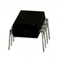
IRS2530DPBF International Rectifier, IRS2530DPBF Datasheet - Page 13

IRS2530DPBF
Manufacturer Part Number
IRS2530DPBF
Description
IC CTRL BALLAST DIMMING 8-DIP
Manufacturer
International Rectifier
Series
DIM8™r
Type
Ballast Controllerr
Datasheet
1.IRS2530DSTRPBF.pdf
(23 pages)
Specifications of IRS2530DPBF
Frequency
34.2 ~ 115 kHz
Current - Supply
5mA
Current - Output
260mA
Voltage - Supply
12.5 V ~ 15.6 V
Operating Temperature
-40°C ~ 125°C
Package / Case
8-DIP (0.300", 7.62mm)
Rohs Compliant
Yes
Peak Reflow Compatible (260 C)
Yes
Supply Current
5mA
Driver Case Style
DIP
No. Of Pins
8
Operating Temperature Range
-40°C To +125°C
Leaded Process Compatible
Yes
For Use With
IRPLDIM5E - KIT DES BALLAST 4LEVEL DIM FLUORIRPLDIM4E - KIT DES BALLAST 26W IRS2530DIRPLCFL8U - KIT DES FLUOR BALLAST IRS2530D
Lead Free Status / RoHS Status
Lead free / RoHS Compliant
Available stocks
Company
Part Number
Manufacturer
Quantity
Price
Company:
Part Number:
IRS2530DPBF
Manufacturer:
IR
Quantity:
3 825
Part Number:
IRS2530DPBF
Manufacturer:
IR
Quantity:
20 000
www.irf.com
until the VB-to-VS voltage exceeds the high-side UVLO rising threshold, V
side driver is enabled. The capacitor CVCC should be large enough such that VCC does not reach UVLO-
before HO is enabled and the charge pump supply takes over.
External gate drive resistors, RHO and RLO, are also recommended as standard design practice to limit high
peak currents that can flow into or out of the HO and LO gate drive outputs.
During UVLO Mode, the high-side gate driver output, HO, is ‘low’ and the VCO pin is pulled down internally
to COM. The low-side gate driver output, LO, is open circuit and is used as a shutdown/reset input function
for automatically restarting the IC when a lamp has been removed and re-inserted. The IC includes an
internal shutdown threshold, V
active during UVLO mode. If VCC is above V
(RLMP1 and RLMP2) will pull LO above V
inserted, the lower filament of the lamp will pull LO down below V
UVLO Mode and enter Preheat/Ignition Mode.
Preheat/Ignition (PH/IGN) Mode
When VCC exceeds V
current source, I
on pin VCO to start ramping up linearly. An additional quick-start current, I
connected to the VCO pin and charges the VCO pin initially to 0.85 V. The quick-start current charges the
VCO voltage up quickly to the internal 1 to 5 V range of the internal VCO. When the VCO voltage exceeds
0.85 V the quick-start current is then disconnected internally and the VCO voltage continues to charge up
with the normal frequency sweep current source, I
The frequency ramps down from the maximum frequency towards the resonance frequency of the high-Q
ballast output stage. The lamp filaments are preheated as the lamp voltage and load current increase. The
voltage on pin VCO continues to increase and the frequency keeps decreasing until the lamp ignites. If the
lamp ignites successfully, the IC will then enter DIM Mode (Figure 3).
VCO
(1 μA, typical), (Figure 2) charges the external capacitor on pin VCO causing the voltage
CCUV+
and the LO pin is below V
DCBUS(+)
DCBUS(-)
DIM REF
and FB
LOSD+
CVCC1
Figure 2, Preheat/Ignition Mode circuitry.
RLIM1
CPH
CVCC2
RLIM2
(8.75 V, typical), and re-start logic circuit at the LO pin that is only
CVCO
CDIM
RVCO
RVCC1
RVCC2
COM
VCC
VCO
DIM
1
2
3
4
LOSD+
4.6V
CLAMP
15.6V
1uA
+
_
Bootstrap
Driver
VCO
FET
CCUV+
and the IC will remain in UVLO mode. When the lamp is re-
Logic
Fault
VCO
Driver
High-
Low-
side
and
13
, but the lamp is removed, the external pull-up network
DCP2
(1 μA, typical) (Figure 3).
8
7
6
5
LOSD-
VB
HO
LO
VS
CBS
RHO
RLO
, the IC enters Preheat/Ignition Mode. An internal
MHS
MLS
CSNUB
DCP1
LOSD-
LOAD RETURN
TO LOAD
(8.5 V, typical) and the IC will exit
BSUV+
VCOQS
(9 V, typical), and the high-
© 2008 International Rectifier
(50 μA, typical), is also
IRS2530D(S)


