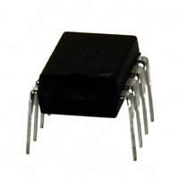
IRS2530DPBF International Rectifier, IRS2530DPBF Datasheet - Page 16

IRS2530DPBF
Manufacturer Part Number
IRS2530DPBF
Description
IC CTRL BALLAST DIMMING 8-DIP
Manufacturer
International Rectifier
Series
DIM8™r
Type
Ballast Controllerr
Datasheet
1.IRS2530DSTRPBF.pdf
(23 pages)
Specifications of IRS2530DPBF
Frequency
34.2 ~ 115 kHz
Current - Supply
5mA
Current - Output
260mA
Voltage - Supply
12.5 V ~ 15.6 V
Operating Temperature
-40°C ~ 125°C
Package / Case
8-DIP (0.300", 7.62mm)
Rohs Compliant
Yes
Peak Reflow Compatible (260 C)
Yes
Supply Current
5mA
Driver Case Style
DIP
No. Of Pins
8
Operating Temperature Range
-40°C To +125°C
Leaded Process Compatible
Yes
For Use With
IRPLDIM5E - KIT DES BALLAST 4LEVEL DIM FLUORIRPLDIM4E - KIT DES BALLAST 26W IRS2530DIRPLCFL8U - KIT DES FLUOR BALLAST IRS2530D
Lead Free Status / RoHS Status
Lead free / RoHS Compliant
Available stocks
Company
Part Number
Manufacturer
Quantity
Price
Company:
Part Number:
IRS2530DPBF
Manufacturer:
IR
Quantity:
3 825
Part Number:
IRS2530DPBF
Manufacturer:
IR
Quantity:
20 000
www.irf.com
that the ignition/preheat ramp will be reset to re-ignite the lamp reliably in case the DC bus decreases too far
and the lamp extinguishes.
Crest Factor Over-current Protection
The IRS2530D uses the VS-sensing circuitry to also measure the low-side half-bridge MOSFET current for
detecting an over-current fault. By using the R
IC eliminates the need for an external current sensing resistor. To cancel changes in the R
temperature and MOSFET variations, the IC performs a crest factor measurement that detects when the
peak current exceeds the average current by a factor of 5.5 (CSCF). Measuring the crest factor is ideal for
detecting when the inductor saturates due to excessive current that occurs in the resonant tank when the
frequency is too close to resonance. During Dim Mode, the crest factor over-current protection is used to
detect if the filaments fail, the lamp is removed, or the lamp becomes deactivated. During each of these fault
conditions, the output stage will transition to a series-LC configuration. The resonant inductor, LRES, and
resonant capacitor, CRES, remain connected together to form a complete circuit due to the voltage-mode
heating configuration to the lamp (see Typical Application Diagram, Page 1). The frequency will move
towards resonance until the inductor saturates.
saturation and the IC will enter Fault Mode and shut down.
Fault Mode and Lamp Reset
During Fault Mode the internal fault latch is set, HO is off, LO is open circuit, and the IC consumes an ultra-
low micro-power current (see State Diagram, Page 11). The IC can be reset with a lamp exchange (as
detected by the LO pin) or a recycling of VCC below and back above the UVLO thresholds. During Fault
Mode, the LO pin is open circuit and is used as an input pin for resetting the IC. If the lamp is removed, the
external pull-up network at the lower lamp filament, RLMP1 and RLMP2 (see Typical Application Diagram,
Page 1), will pull LO above V
When the lamp is re-inserted, the lower filament of the lamp will pull LO down below V
and the IC will exit UVLO Mode and enter Preheat/Ignition Mode and restart the lamp.
I
I
MHS
LOSD+
MLS
HO
LO
VS
I
L
Figure 5, Non-ZVS protection timing diagram.
!
(8.75V, typical) and the IC will exit Fault Mode and enter UVLO mode.
Too close to resonance.
Hard-switching and high
peak MOSFET currents!
!
DSon
!
of the external low-side MOSFET for current sensing, the
The crest factor protection circuit will then detect the
16
Frequency shifted higher
to maintain ZVS.
© 2008 International Rectifier
IRS2530D(S)
LOSD-
DSon
(8.5V, typical)
value due to


