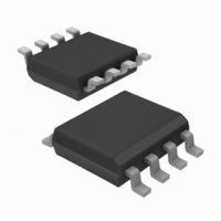
IRS2608DSPBF International Rectifier, IRS2608DSPBF Datasheet - Page 11

IRS2608DSPBF
Manufacturer Part Number
IRS2608DSPBF
Description
IC DVR HALF BRIDGE 600V 8-SOIC
Manufacturer
International Rectifier
Datasheet
1.IRS2608DSTRPBF.pdf
(23 pages)
Specifications of IRS2608DSPBF
Configuration
Half Bridge
Input Type
Differential
Delay Time
250ns
Current - Peak
200mA
Number Of Configurations
1
Number Of Outputs
2
High Side Voltage - Max (bootstrap)
600V
Voltage - Supply
10 V ~ 20 V
Operating Temperature
-40°C ~ 125°C
Mounting Type
Surface Mount
Package / Case
8-SOIC (3.9mm Width)
Lead Free Status / RoHS Status
Lead free / RoHS Compliant
Integrated Bootstrap Functionality
The IRS2608D embeds an integrated bootstrap FET that allows an alternative drive of the bootstrap supply for a wide
range of applications. A bootstrap FET is connected between the floating supply V
The summary for the bootstrap state follows:
The bootstrap FET is suitable for complimentary PWM switching schemes only. Complimentary PWM refers to
PWM schemes where the HIN & LIN input signals are alternately switched on and off. IRS2608D is suitable for
sinusoidal motor control and the integrated bootstrap feature can be used either in parallel with the external
bootstrap network (diode and resistor) or as a replacement of it. The use of the integrated bootstrap as a
replacement of the external bootstrap network may have some limitations at very high PWM duty cycle,
corresponding to very short LIN pulses, due to the bootstrap FET equivalent resistance RBS. IRS2608D is NOT
recommended for trapezoidal motor control, even if an external bootstrap network is employed in parallel.
•
•
www.irf.com
Bootstrap turns-off (immediately) or stays off when at least one of the following conditions are met:
Bootstrap turns-on when:
1- HO goes/is high
2- V
1- LO is high (low side is on) AND V
2- LO and HO are low after a LIN transition from H to L (HB output is in tri-state) AND V
(<1.1*V
3- LO and HO are low after a HIN transition from H to L (HB output is in tri-state) AND V
(<1.1(V
VB goes high (>1.1V
B
goes/is high (> 1.1*V
CC
CC
)) before a retriggerable time of 20us. In this case the time counter is kept in reset state until
) before a fixed time of 20us.
CC
Figure 8: Semplified BootFET connection
). Please refer to the BootFET timing diagram for more details.
Vcc
CC
)
B
is low (< 1.1(V
BootFet
CC
))
Vb
B
and V
CC
(see Fig. 8).
IRS2608DSPbF
B
B
goes low
goes low
11


