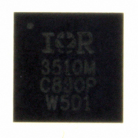
IR3510MTRPBF International Rectifier, IR3510MTRPBF Datasheet - Page 30

IR3510MTRPBF
Manufacturer Part Number
IR3510MTRPBF
Description
IC XPHASE CONTROL 32-MLPQ
Manufacturer
International Rectifier
Series
XPhase™r
Datasheet
1.IR3510MTRPBF.pdf
(36 pages)
Specifications of IR3510MTRPBF
Applications
Processor
Mounting Type
Surface Mount
Package / Case
32-MLPQ
Package
32-Lead MLPQ
Circuit
X-Phase Control IC
Pbf
PbF Option Available
Lead Free Status / RoHS Status
Lead free / RoHS Compliant
Current - Supply
-
Voltage - Supply
-
Operating Temperature
-
Other names
IR3510MTRPBFTR
Available stocks
Company
Part Number
Manufacturer
Quantity
Price
Part Number:
IR3510MTRPBF
Manufacturer:
IR
Quantity:
20 000
In order to eliminate the inductor from the voltage loop, the current loop cross-over frequency needs to be much
higher than the L-C resonant frequency. Meanwhile, it has to be less than 1/5 of the switching frequency. So, the
current loop cross-over frequency can be placed between 3Fo and 1/5Fs.
Typical Type II compensation can be used with the compensation zero placed at the L-C double pole frequency
and high frequency pole placed near the switching frequency. The cross-over frequency determines the middle
frequency gain.
Assuming Lo is the equivalent output inductance for multiple phases, Rpwm and Cpwm set the PWM RAMP with
the phase IC, Fs is the switching frequency, Ki is the current feedback gain which is defined by Vimax/Iomax,
select the current EA compensation gain at the cross-over frequency to be,
where,
Select Rcfb = 1K, then,
Voltage Error Amplifier Compensation and Vdroop setting
The inner current loop removes the output inductor from the voltage loop, so the open voltage loop has only one
pole, which is made by the output cap and load resistor, up to the current loop cross-over frequency. To avoid the
interference between the outer voltage loop and the inner current loop, the voltage loop cross-over frequency
should be placed at least 10KHz below the current loop cross-over frequency.
Typical type II compensation can be used with the compensation zero placed at the output pole and the high-
frequency pole placed at the ESR zero of the output cap. The compensation middle-frequency gain determines
the voltage loop cross-over frequency. It can be calculated as follows,
where, Fcv is the target voltage loop cross-over frequency
The Type III compensation is only needed if the voltage loop cross-over frequency has to be greater than the
current loop cross-over frequency in some applications. It can improve the phase margin.
The voltage droop is determined by the voltage error amplifier compensation DC gain, which is set by the
feedback resistor Rdrp across the voltage error amplifier. Rdrp can be calculated as follows,
Select Rvfb = 1K, then,
Kv is the voltage feedback gain. Without feedback resistor divider, It’s a unity gain.
Page 30 of 36
Gpwm is the PWM gain of the power stage, Gpwm = Rpwm*Cpwm*Fs
Fci is the target current loop cross-over frequency
Kcv
Kci
Ccc = 1/ (2π*Rcc*Fo)
Ccp = 1/ (2π*Rcc*Fs)
Cvc = 1/ (2π*Rvc*Fo)
Cvcp = 1/ (2π*Rvc*Fesr)
Rcc = Kci
Rvc = Kcv
=
=
2
2
Gpwm
π
π
*
*
Co
Lo
(K Ohm)
(K Ohm)
IR Confidential
Kv
*
*
*
Fci
Ki
Ki
*
Fcv
May 18, 2009
IR3510


