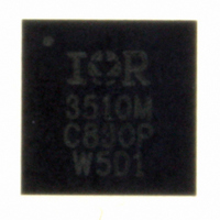
IR3510MTRPBF International Rectifier, IR3510MTRPBF Datasheet - Page 31

IR3510MTRPBF
Manufacturer Part Number
IR3510MTRPBF
Description
IC XPHASE CONTROL 32-MLPQ
Manufacturer
International Rectifier
Series
XPhase™r
Datasheet
1.IR3510MTRPBF.pdf
(36 pages)
Specifications of IR3510MTRPBF
Applications
Processor
Mounting Type
Surface Mount
Package / Case
32-MLPQ
Package
32-Lead MLPQ
Circuit
X-Phase Control IC
Pbf
PbF Option Available
Lead Free Status / RoHS Status
Lead free / RoHS Compliant
Current - Supply
-
Voltage - Supply
-
Operating Temperature
-
Other names
IR3510MTRPBFTR
Available stocks
Company
Part Number
Manufacturer
Quantity
Price
Part Number:
IR3510MTRPBF
Manufacturer:
IR
Quantity:
20 000
where, Iomax is the rated maximum output current
Current Report Gain and Thermal Compensation
The inductor DC resistance is utilized to sense the inductor current. The copper wire of inductor has a constant
temperature coefficient of 3850 ppm/° C, and therefore the maximum inductor DCR can be calculated,
Where, R
T_
The total input offset voltage (V
(V
sense resistor R
The current sense signal IIN received from phase IC is determined by,
Where,
The current report signal Io is determined by,
Where, the 0.2V offset voltage is added inside the IR3510 so it can measure the reverse current
compensation network.
Rcr3 in series with Rcrt which is a NTC provides thermal compensation to cancel the TC effect of the inductor
DCR. Place the NTC close to the output inductor of the center phase.
Oring Reverse Current Cut-Off Threshold setting resistor
The Oring FET reverse current is sensed by the Rds(on) of the Oring FET. The reverse current cut-off threshold
programming resistor Rorset is connected between the Drain pin of the Oring FET and the “OR-“ pin. A constant
current source Iorset flowing out of the “OR--“ pin goes through Rorset and sets the reverse current cut-off
threshold voltage.
CS_OFST)
ROOM.
Rfb is the resistor connected to the inverting input of the voltage error amplifier
Vdrp is the required droop voltage at rated maximum output current.
Rcr1 is the resistor connected from “IGAIN” pin to GND.
Rcr2 is the external equivalent resistance between “IGAIN” pin and “IO” pin, which includes the thermal
Page 31 of 36
L_MAX
of the amplifier itself and that created by the amplifier input bias current flowing through the current
CS
and R
.
Io
Iomax = Maximum load current
N = Number of phases
G
L_ROOM
CS
=
= Gain of the current sense amplifier
{[
V
Rdrp
R
IIN
CS
L
Io
are the inductor DCR at maximum temperature T
_
CS_TOFST
_
MAX
TOFST
max
=
n
=
Vref
=
Ki
=
R
∗
*
L
V
) of current sense amplifier in the phase ICs is the sum of input offset
_
CS
+
Io
R
ROOM
Vdrp
[
_
L
max*
Io
OFST
_
IR Confidential
MAX
max
N
∗
1 [
+
Rfb
I
+
+
CSIN
∗
3850
V
R
CS
+
L
∗
_
*
MAX
_
R
10
TOFST
CS
−
6
+
∗
V
(
]
T
CS
∗
L
_
_
G
TOFST
MAX
CS
−
]
+
T
∗
ROOM
. 0
G
} 2
CS
)]
*
L_MAX
1 (
+
Rcr
and room temperature
May 18, 2009
/ 2
IR3510
Rcr
) 1


