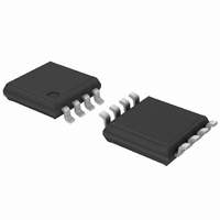
SA56004EDP,118 NXP Semiconductors, SA56004EDP,118 Datasheet - Page 13

SA56004EDP,118
Manufacturer Part Number
SA56004EDP,118
Description
IC TEMP SENSOR 8-TSSOP
Manufacturer
NXP Semiconductors
Datasheet
1.SA56004BDP118.pdf
(36 pages)
Specifications of SA56004EDP,118
Package / Case
8-TSSOP
Output Type
I²C™/SMBus™
Function
Temp Monitoring System (Sensor)
Topology
ADC (Sigma Delta), Multiplexer, Register Bank
Sensor Type
External & Internal
Sensing Temperature
-40°C ~ 125°C, External Sensor
Output Alarm
Yes
Output Fan
Yes
Voltage - Supply
3 V ~ 3.6 V
Operating Temperature
-40°C ~ 125°C
Mounting Type
Surface Mount
Supply Voltage (max)
5.5 V
Supply Voltage (min)
3 V
Maximum Operating Temperature
+ 125 C
Minimum Operating Temperature
- 40 C
Supply Current
1 mA
Lead Free Status / RoHS Status
Lead free / RoHS Compliant
For Use With
568-3615 - DEMO BOARD I2C
Lead Free Status / Rohs Status
Lead free / RoHS Compliant
Other names
568-3338-2
935274567118
SA56004EDP-T
935274567118
SA56004EDP-T
NXP Semiconductors
SA56004X_5
Product data sheet
7.9.1.3 ALERT output in SMBus ALERT mode
The following events summarize the ALERT output interrupt mode of operation:
When several slave devices share a common interrupt line, an SMBus alert line is
implemented. The SA56004X is designed to accommodate the Alert interrupt detection
capability of the SMBus 2.0 Alert Response Address (ARA) protocol, defined in SMBus
specification 2.0 . This procedure is designed to assist the master in resolving which slave
device generated the interrupt and in servicing the interrupt while minimizing the time to
restore the system to its proper operation. Basically, the SMBus provides Alert response
interrupt pointers in order to identify slave devices which have caused the Alert interrupt.
When the ARA command is received by all devices on the SMBus, the devices pulling the
SMBus alert line LOW send their device addresses to the master; await an
acknowledgement and then release the alert line. This requirement to disengage the
SMBus alert line prevents locking up the alert line. The SA56004X complies with this ARA
disengagement protocol by setting the ALERT mask bit 7 in the Configuration register at
address 09h after successfully sending out its address in response to an ARA command
and releasing the ALERT output. Once the mask bit is activated, the ALERT output will be
disabled until enabled by software. In order to enable the ALERT the master must read the
Fig 5.
Event A: Master senses ALERT output being active-LOW.
Event B: Master reads the SA56004X Status register to determine what cause the
ALERT interrupt.
Event C: SA56004X clears the Status register, resets the ALERT output HIGH, and sets
the ALERT mask bit 7 in the Configuration register.
Event D: A new conversion result indicates the temperature is still above the high limit,
however the ALERT pin is not activated due to the ALERT mask.
Event E: Master should correct the conditions that caused the ALERT output to be
triggered. For instance, the fan is started, setpoint levels are adjusted.
Event F: Master resets the ALERT mask bit 7 in the Configuration register.
remote temperature high limit
ALERT output in interrupt mode
remote diode temperature
status register bit 4
ALERT pin
(RHIGH)
Rev. 05 — 22 May 2008
Digital temperature sensor with overtemperature alarms
A
B, C
D
SA56004X
© NXP B.V. 2008. All rights reserved.
002aad216
E, F
13 of 36


