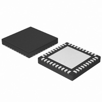
NCP4200MNR2G ON Semiconductor, NCP4200MNR2G Datasheet - Page 19

NCP4200MNR2G
Manufacturer Part Number
NCP4200MNR2G
Description
IC CONV SYNC BUCK PMBUS 40QFN
Manufacturer
ON Semiconductor
Datasheet
1.NCP4200MNR2G.pdf
(32 pages)
Specifications of NCP4200MNR2G
Applications
Converter, Intel VR11, VR11.1
Voltage - Input
1.7 ~ 24 V
Number Of Outputs
1
Voltage - Output
0.375 ~ 1.8 V
Operating Temperature
0°C ~ 85°C
Mounting Type
Surface Mount
Package / Case
40-VFQFN Exposed Pad
Output Voltage
0.375 V to 1.6 V
Output Current
500 uA
Input Voltage
1.7 V to 24 V
Switching Frequency
0.25 MHz to 6 MHz
Operating Temperature Range
0 C to + 85 C
Mounting Style
SMD/SMT
Duty Cycle (max)
100 %
Isolated/non-isolated
Non Isolated
Lead Free Status / RoHS Status
Lead free / RoHS Compliant
Available stocks
Company
Part Number
Manufacturer
Quantity
Price
Company:
Part Number:
NCP4200MNR2G
Manufacturer:
PHILIPS
Quantity:
124
faults. This operation is shown in Figure 14.
immediately after setting up the address, it can assert a repeat
start condition immediately after the final ACK and carry
out a single byte read without asserting an intermediate stop
condition.
Write Byte
and one data byte to the slave device as follows:
The byte write operation is shown in Figure 15.
Write Word
and two data bytes to the slave device as follows:
The word write operation is shown in Figure 16.
For the NCP4200, the send byte protocol is used to clear
If the master is required to read data from the register
In this operation, the master device sends a command byte
In this operation, the master device sends a command byte
10. The master asserts a stop condition on SDA and
1. The master device asserts a start condition on
2. The master sends the 7−bit slave address followed
3. The addressed slave device asserts ACK on SDA.
4. The master sends a command code.
5. The slave asserts ACK on SDA.
6. The master sends a data byte.
7. The slave asserts ACK on SDA.
8. The master asserts a stop condition on SDA and
1. The master device asserts a start condition on
2. The master sends the 7−bit slave address followed
3. The addressed slave device asserts ACK on SDA.
4. The master sends a command code.
5. The slave asserts ACK on SDA.
6. The master sends the first data byte.
7. The slave asserts ACK on SDA.
8. The master sends the second data byte.
9. The slave asserts ACK on SDA.
Figure 16. Single Word Write to a Register
Figure 15. Single Byte Write to a Register
1
S
SDA.
by the write bit (low).
the transaction ends.
SDA.
by the write bit (low).
the transaction ends.
ADDRESS
SLAVE
1
S
Figure 14. Send Byte Command
2
ADDRESS
SLAVE
1
S
2
ADDRESS
W
SLAVE
3
A
2
W
COMMAND
A
3
CODE
W
4
COMMAND
A
3
CODE
4
COMMAND
CODE
5
A
4
(LSB)
DATA
6
5
A
DATA
7
A
6
5
A
(MSB)
6
P
DATA
A
8
7
P
8
9
A
10
P
http://onsemi.com
19
Block Write
and a byte count followed by the stated number of data bytes
to the slave device as follows:
Read Operations
Read Byte
from a slave device as follows:
In this operation, the master device sends a command byte
The NCP4200 uses the following I
In this operation, the master device receives a single byte
S
1
10. The master sends the second data byte.
12. The master sends the remainder of the data byes
13. The slave asserts an ACK on SDA after each data
14. After the last data byte the master asserts a STOP
10. The master asserts NO ACK on SDA.
11. The slave asserts ACK on SDA
11. The master asserts a stop condition on SDA and
S
1
1. The master device asserts a START condition on
2. The master sends the 7−bit slave address followed
3. The addressed slave device asserts ACK on SDA.
4. The master sends a command code
5. The slave asserts ACK on SDA
6. The master sends the byte count N
7. The slave asserts ACK on SDA
8. The master sends the first data byte
9. The slave asserts ACK on SDA
1. The master device asserts a start condition on
2. The master sends the 7−bit slave address followed
3. The addressed slave device asserts ACK on SDA.
4. The master sends a command code.
5. The slave asserted ACK on SDA.
6. The master sends a repeated start condition on
7. The master sends the 7 bit slave address followed
8. The slave asserts ACK on SDA.
9. The slave sends the Data Byte.
ADDRESS
Figure 18. Single Byte Read from a Register
ADDRESS
SLAVE
SLAVE
SDA.
by the write bit (low).
byte.
condition on SDA
SDA.
by the write bit (low).
SDA.
by the read bit (high).
the transaction ends.
2
2
Figure 17. Block Write to a Register
W
W
BYTE 2
DATA
3
A
10
3
A
COMMAND
COMMAND
CODE
CODE
11
4
A
4
...
...
A
5
A
5
S
BYTE N
6
BYTE COUNT
DATA
ADDRESS
12
SLAVE
= N
7
6
2
C read protocols.
13
A
R
14
P
A
7
A
8
BYTE 1
DATA
DATA
9
8
10
A
A
9
11
P


