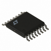
LT1940EFE#TR Linear Technology, LT1940EFE#TR Datasheet - Page 13

LT1940EFE#TR
Manufacturer Part Number
LT1940EFE#TR
Description
IC REG SW DUAL 1.4A STDN 16TSSOP
Manufacturer
Linear Technology
Type
Step-Down (Buck)r
Datasheet
1.LT1940EFEPBF.pdf
(20 pages)
Specifications of LT1940EFE#TR
Internal Switch(s)
Yes
Synchronous Rectifier
No
Number Of Outputs
2
Voltage - Output
1.25 ~ 22 V
Current - Output
1.4A
Frequency - Switching
1.1MHz
Voltage - Input
3.6 ~ 25 V
Operating Temperature
-40°C ~ 85°C
Mounting Type
Surface Mount
Package / Case
16-TSSOP Exposed Pad, 16-eTSSOP, 16-HTSSOP
Lead Free Status / RoHS Status
Contains lead / RoHS non-compliant
Power - Output
-
Available stocks
Company
Part Number
Manufacturer
Quantity
Price
Soft-Start and Shutdown
The RUN/SS (Run/Soft-Start) pins are used to place the
individual switching regulators and the internal bias cir-
cuits in shutdown mode. They also provide a soft-start
function. To shut down either regulator, pull the RUN/SS
pin to ground with an open-drain or collector. If both
RUN/SS pins are pulled to ground, the LT1940 enters its
shutdown mode with both regulators off and quiescent
current reduced to ~30 A. Internal 2 A current sources
pull up on each pin. If either pin reaches ~0.5V, the internal
bias circuits start and the quiescent current increases to
~3.5mA.
If a capacitor is tied from the RUN/SS pin to ground, then
the internal pull-up current will generate a voltage ramp on
this pin. This voltage clamps the V
switch current and therefore input current during start up.
A good value for the soft-start capacitor is C
where C
The RUN/SS pins can be left floating if the shutdown
feature is not used. They can also be tied together with a
single capacitor providing soft-start. The internal current
sources will charge these pins to ~2.5V.
The RUN/SS pins provide a soft-start function that limits
peak input current to the circuit during start-up. This helps
to avoid drawing more current than the input source can
supply or glitching the input supply when the LT1940 is
enabled. The RUN/SS pins do not provide an accurate
delay to start or an accurately controlled ramp at the
output voltage, both of which depend on the output
capacitance and the load current. However, the power
good indicators can be used to sequence the two outputs,
as described below.
Power Good Indicators
The PG pin is the open collector output of an internal
comparator. PG remains low until the FB pin is within 10%
of the final regulation voltage. Tie the PG pin to any supply
with a pull-up resistor that will supply less than 250 A.
Note that this pin will be open when the LT1940 is placed
in shutdown mode (both RUN/SS pins at ground) regard-
less of the voltage at the FB pin. Power good is valid when
APPLICATIO S I FOR ATIO
OUT
is the value of the output capacitor.
U
U
C
W
pin, limiting the peak
OUT
U
/10,000,
the LT1940 is enabled (either RUN/SS pin is high) and V
is greater than ~2.4V.
Output Sequencing
The PG and RUN/SS pins can be used to sequence the two
outputs. Figure 5 shows several circuits to do this. In each
case channel 1 starts first. Note that these circuits se-
quence the outputs during start-up. When shut down the
two channels turn off simultaneously.
In Figure 5a, a larger capacitor on RUN/SS2 delays chan-
nel 2 with respect to channel 1. The soft-start capacitor on
RUN/SS2 should be at least twice the value of the capacitor
on RUN/SS1. A larger ratio may be required, depending on
the output capacitance and load on each channel. Make
sure to test the circuit in the system before deciding on
final values for these capacitors.
The circuit in Figure 5b requires the fewest components,
with both channels sharing a single soft-start capacitor.
The power good comparator of channel 1 disables channel
2 until output 1 is in regulation.
For independent control of channel 2, use the circuit in
Figure 5c. The capacitor on RUN/SS1 is smaller than the
capacitor on RUN/SS2. This allows the LT1940 to start up
and enable its power good comparator before RUN/SS2
gets high enough to allow channel 2 to start switching.
Channel 2 only operates when it is enabled with the
external control signals and output 1 is in regulation.
The circuit in Figure 5a leaves both power good indicates
free. However, the circuits in Figures 5b and 5c have
another advantage. As well as sequencing the two outputs
at start-up, they also disable channel 2 if output 1 falls out
of regulation (due to a short circuit or a collapsing input
voltage).
Finally, be aware that the circuit in Figure 5d does not
work, because the power good comparators are disabled
in shutdown. When the system is placed in shutdown
mode by pulling down on RUN/SS1, then output 1 will go
low, PG1 will pull down on RUN/SS2, and the LT1940 will
enter its low current shutdown state. This disables PG1,
and RUN/SS2 ramps up again to enable the LT1940. The
circuit will oscillate and pull extra current from the input.
LT1940/LT1940L
13
1940fa
IN


