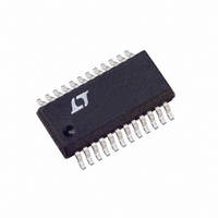
LTC3736EGN-1 Linear Technology, LTC3736EGN-1 Datasheet - Page 16

LTC3736EGN-1
Manufacturer Part Number
LTC3736EGN-1
Description
IC CTRLR SW SYNC DUAL 2PH 24SSOP
Manufacturer
Linear Technology
Series
PolyPhase®r
Type
Step-Down (Buck)r
Datasheet
1.LTC3736EGN-1.pdf
(28 pages)
Specifications of LTC3736EGN-1
Internal Switch(s)
No
Synchronous Rectifier
Yes
Number Of Outputs
2
Voltage - Output
0.6 ~ 9.8 V
Current - Output
1A
Frequency - Switching
450kHz ~ 580kHz
Voltage - Input
2.75 ~ 9.8 V
Operating Temperature
-40°C ~ 85°C
Mounting Type
Surface Mount
Package / Case
24-SSOP
Lead Free Status / RoHS Status
Contains lead / RoHS non-compliant
Power - Output
-
APPLICATIO S I FOR ATIO
LTC3736-1
Operating Frequency
When spread spectrum operation is enabled (SSDIS =
GND), the frequency of the LTC3736-1 is randomly varied
over the range of frequencies between 450kHz and 580kHz.
In this case, a capacitor (1nF to 4.7nF) should be connected
between the FREQ pin and SGND (or V
changes in frequency. This not only provides a smoother
frequency spectrum but also ensures that the switching
regulator remains stable by preventing abrupt changes
in frequency. A value of 2200pF is suitable in most
applications.
When the spread spectrum operation is disabled (SSDIS =
V
among three discrete, constant frequencies using the FREQ
pin. Floating the FREQ pin selects 550kHz operation; tying
this pin to V
selects 300kHz. Table 2 summarizes the different states in
which the FREQ pin can be used.
Table 2
FREQ PIN
0V
Floating
V
Capacitor to GND
or V
Note that when spread spectrum operation is disabled, the
LTC3736-1 operates like the standard, constant frequency
LTC3736, except that at light loads, the LTC3736-1 oper-
ates in pulse skipping mode. This mode is not available on
the LTC3736 unless the device is synchronized to an ex-
ternal clock signal using its phase-locked loop (PLL). Thus,
if an LTC3736 with pulse skipping function is needed, then
the LTC3736-1 with spread spectrum disabled is the appro-
priate solution. Table 3 summarizes the key differences in
the available features on the LTC3736 and LTC3736-1.
Table 3
AVAILABLE FEATURES/OPTIONS
Selectable Constant Frequency
Spread Spectrum
Synchronizable (PLL)
Burst Mode
Forced Continuous Mode
Pulse Skipping Mode
16
IN
IN
IN
), the LTC3736-1’s frequency may be selected from
®
IN
selects 750kHz, while tying this pin to GND
SSDIS PIN
GND
U
V
V
V
IN
IN
IN
U
Spread Spectrum (450kHz to 580kHz)
When Synchronized
LTC3736
Yes
Yes
Yes
Yes
W
No
IN
FREQUENCY
) to smooth out the
300kHz
550kHz
750kHz
U
LTC3736-1
Yes
Yes
Yes
No
No
No
Inductor Value Calculation
Given the desired input and output voltages, the inductor
value and operating frequency f
inductor’s peak-to-peak ripple current:
Lower ripple current reduces core losses in the inductor,
ESR losses in the output capacitors, and output voltage
ripple. Thus, highest efficiency operation is obtained at
low frequency with a small ripple current. Achieving this,
however, requires a large inductor.
A reasonable starting point is to choose a ripple current
that is about 40% of I
current occurs at the highest input voltage. To guarantee
that ripple current does not exceed a specified maximum,
the inductor should be chosen according to:
Inductor Core Selection
Once the inductance value is determined, the type of
inductor must be selected. High efficiency converters
generally cannot afford the core loss found in low cost
powdered iron cores, forcing the use of ferrite, molyper-
malloy or Kool Mµ
of core size for a fixed inductor value, but it is very
dependent on inductance selected. As inductance in-
creases, core losses go down. Unfortunately, increased
inductance requires more turns of wire and therefore
copper losses will increase.
Ferrite designs have very low core loss and are preferred
at high switching frequencies, so design goals can
concentrate on copper loss and preventing saturation.
Ferrite core material saturates “hard,” which means that
inductance collapses abruptly when the peak design cur-
rent is exceeded. This results in an abrupt increase in
inductor ripple current and consequent output voltage
ripple. Do not allow the core to saturate!
Burst Mode is a registered trademark of Linear Technology Corporation.
Kool Mµ is a registered trademark of Magnetics, Inc.
I
L
RIPPLE
≥
f
OSC RIPPLE
V
IN
=
–
•
V
I
V
V
OUT
IN
OUT
®
⎛
⎜
⎝
cores. Actual core loss is independent
V
OUT(MAX)
•
IN
f
OSC
V
V
–
OUT
IN
V
•
OUT
L
. Note that the largest ripple
OSC
⎞
⎟
⎠
directly determine the
37361f


